M20D-FKS ENGINE MECHANICAL REAR CRANKSHAFT OIL SEAL INSTALLATION
CAUTION / NOTICE / HINT
- NOTICE:
-
This procedure includes the installation of small-head bolts. Refer to Small-Head Bolts of Basic Repair Hint to identify the small-head bolts.
PROCEDURE

 11401L
1.INSTALL REAR ENGINE OIL SEAL
11401L
1.INSTALL REAR ENGINE OIL SEAL
Using height adjustment attachments and plate lift attachments, place the engine assembly on a flat level surface.
- NOTICE:
- ·
Using height adjustment attachments and plate lift attachments, keep the engine assembly level.
·To prevent the No. 2 oil pan sub-assembly from deforming, do not place any attachments under the No. 2 oil pan sub-assembly of the engine assembly.
·Using an engine sling device and engine lift, secure the engine assembly before servicing.
Apply MP grease to the lip of a new rear engine oil seal.
- NOTICE:
- ·
Keep the lip free from foreign matter.
·Do not allow MP grease to contact the dust seal.
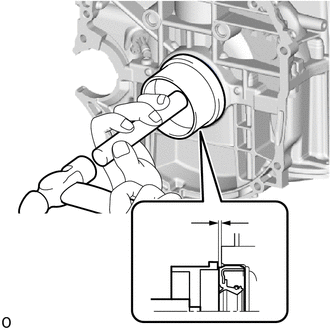
| *a | -0.9 to 1.1 mm |
Using SST and a hammer, tap in the rear engine oil seal.
- SST
- 09223-15030
09950-70010 (09951-07150)
- Standard Depth:
-0.9 to 1.1 mm (-0.0354 to 0.0433 in.) (From the edge of the cylinder block sub-assembly and stiffening crankcase assembly)
- NOTICE:
-
Do not tap in the rear engine oil seal at an angle.
19315
2.INSTALL NO. 1 CRANKSHAFT POSITION SENSOR PLATE
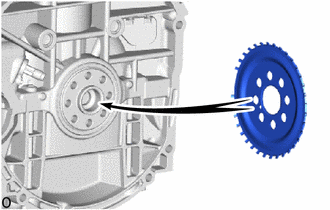
Install the No. 1 crankshaft position sensor plate.
- HINT:
-
Align the pin hole of the No. 1 crankshaft position sensor plate with the pin of the crankshaft.
32101B
3.INSTALL DRIVE PLATE AND RING GEAR SUB-ASSEMBLY
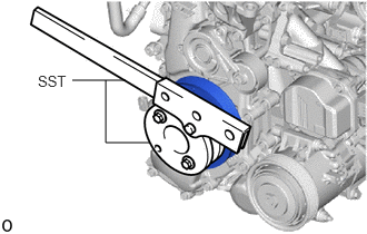
Using SST, hold the crankshaft pulley assembly.
- SST
- 09213-54015
09330-00021
Clean the 8 bolts and bolt holes.
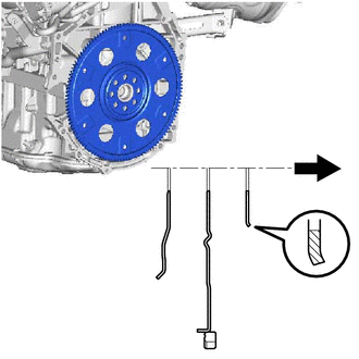
| *1 | Drive Plate and Ring Gear Sub-assembly |
| *2 | Rear Drive Plate Spacer |
| *3 | No. 1 Crankshaft Position Sensor Plate |

|
Transaxle Side |
Install the drive plate and ring gear sub-assembly and rear drive plate spacer to the crankshaft.
- NOTICE:
-
As the rear drive plate spacer, drive plate and ring gear sub-assembly and No. 1 crankshaft position sensor plate are not reversible, be sure to install them so that they are facing in the direction shown in the illustration.
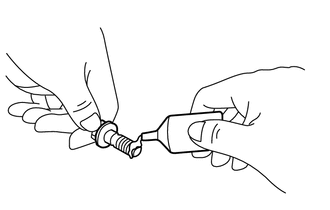
| *a | Adhesive |
Apply a few drops of adhesive to 2 or 3 threads at the tip of each of 8 bolts.
- Adhesive:
Toyota Genuine Adhesive 1324, Three Bond 1324 or equivalent
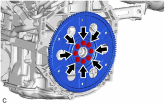
Install and uniformly tighten the 8 bolts in the sequence shown in the illustration.
- Torque:
- 150 N*m (1530 kgf*cm, 111 ft.*lbf)
- NOTICE:
- ·
Handle the drive plate installation bolts carefully. Do not scratch them or subject them to any shocks.
·Do not start the engine for at least 1 hour after installing the drive plate and ring gear sub-assembly.
30400
4.INSTALL CONTINUOUSLY VARIABLE TRANSAXLE ASSEMBLY