K121F CVT CONTINUOUSLY VARIABLE TRANSAXLE ASSEMBLY INSTALLATION
CAUTION / NOTICE / HINT
- CAUTION:
-
The engine assembly with continuously variable transaxle assembly is very heavy. Be sure to follow the procedure described in the repair manual, or the engine lifter may suddenly drop.
PROCEDURE

 36100A
1.INSTALL TRANSFER AND TRANSAXLE SETTING STUD BOLT
36100A
1.INSTALL TRANSFER AND TRANSAXLE SETTING STUD BOLT
- HINT:
-
It is not necessary to remove the transfer and transaxle setting stud bolts unless they are being replaced.
for Transfer Side:
for Continuously Variable Transaxle Assembly Side:
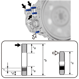
| *a | 22 mm (0.866 in.) |
| *b | 69 mm (2.72 in.) |
| *c | 5.0 to 7.5 mm (0.200 to 0.300 in.) |
| *d | 13 mm (0.512 in.) |
| *e | 47 mm (1.85 in.) |

|
Sealant |

|
Adhesive 1324 |

|
Transfer and Transaxle Setting Stud Bolt A |

|
Transfer and Transaxle Setting Stud Bolt B |
Clean the transfer and transaxle setting stud bolt holes.
for Transfer and Transaxle Setting Stud Bolt A:
Apply adhesive 1324 to 2 or 3 threads on one half of 3 new transfer and transaxle setting stud bolts A as shown in the illustration.
- Adhesive:
Toyota Genuine Adhesive 1324, Three Bond 1324 or equivalent
- NOTICE:
- ·
Do not apply adhesive 1324 to the ends of the transfer and transaxle setting stud bolts A.
·Install the transfer and transaxle setting stud bolts A immediately after applying adhesive 1324 to prevent the adherence of foreign matter.
·Install the transfer and transaxle setting stud bolts A so that the side that has adhesive 1324 is facing the continuously variable transaxle assembly.
Install the 3 transfer and transaxle setting stud bolts A to the continuously variable transaxle assembly positions shown in the illustration.
- Torque:
39.2 N*m (400 kgf*cm, 29 ft.*lbf)
for Transfer and Transaxle Setting Stud Bolt B:
Install a new transfer and transaxle setting stud bolt B to the continuously variable transaxle assembly positions shown in the illustration.
- Torque:
39.2 N*m (400 kgf*cm, 29 ft.*lbf)
- NOTICE:
-
Install the transfer and transaxle setting stud bolt B so that the side that has sealant is facing the continuously variable transaxle assembly.
36100
2.INSTALL TRANSFER ASSEMBLY
3.INSTALL BREATHER PLUG SUB-ASSEMBLY
- HINT:
-
Perform this procedure only when replacement of the breather plug sub-assembly is necessary.
Coat a new O-ring with Toyota Genuine CVT fluid FE and install it to the breather plug.
- NOTICE:
-
Ensure that the O-ring is not twisted.
Install the breather plug cap to the breather plug.
Install the breather plug sub-assembly to the continuously variable transaxle assembly.
- NOTICE:
-
Be careful not to damage the O-ring.
35150B
4.INSTALL TRANSMISSION CASE PLUG ASSEMBLY
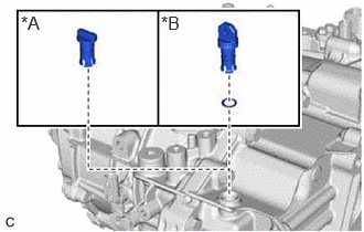
| *A | for Type A |
| *B | for Type B |
for Type A:
Install the transmission case plug assembly to the continuously variable transaxle assembly.
- NOTICE:
-
Be careful not to damage the O-ring.
for Type B:
Coat a new O-ring with Toyota Genuine CVT fluid FE and install it to the transmission case plug assembly.
- NOTICE:
-
Ensure that the O-ring is not twisted.
Install the transmission case plug assembly to the continuously variable transaxle assembly.
- NOTICE:
-
Be careful not to damage the O-ring.
33823
5.INSTALL NO. 1 TRANSMISSION CONTROL CABLE BRACKET
Install the No. 1 transmission control cable bracket to the continuously variable transaxle assembly with the 2 bolts.
- Torque:
- 12 N*m (122 kgf*cm, 9 ft.*lbf)
16575B
6.INSTALL NO. 2 WATER HOSE CLAMP BRACKET
Install the No. 2 water hose clamp bracket to the continuously variable transaxle assembly with the 2 bolts.
- Torque:
- 19 N*m (194 kgf*cm, 14 ft.*lbf)
7.INSTALL WIRE HARNESS CLAMP BRACKET
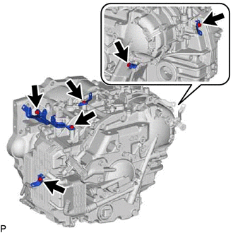
Install the 5 wire harness clamp brackets to the continuously variable transaxle assembly with the 6 bolts.
- Torque:
- 10 N*m (102 kgf*cm, 7 ft.*lbf)
12304
8.INSTALL ENGINE MOUNTING BRACKET SUB-ASSEMBLY LH
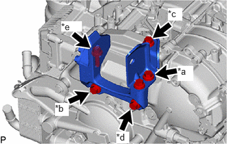
| *a | Bolt A |
| *b | Bolt B |
| *c | Bolt C |
| *d | Bolt D |
| *e | Bolt E |
Install the engine mounting bracket sub-assembly LH to the continuously variable transaxle assembly with the 5 bolts.
- Torque:
- 42 N*m (428 kgf*cm, 31 ft.*lbf)
- HINT:
-
Tightening order: Temporarily install bolt (A) → Tighten bolt (B) → Tighten bolt (D) → Tighten bolt (A) → Tighten bolt (C) → Tighten bolt (E)
9.INSTALL TRANSAXLE HOUSING TYPE T OIL SEAL
Ensure that there is no dirt or foreign matter on your hands and then apply MP grease to the entire periphery of the lip of a new transaxle housing type T oil seal.
Temporarily install the transaxle housing type T oil seal by pressing it to the installation surface of the oil pump housing by hand.
- NOTICE:
-
Be sure to install the transaxle housing type T oil seal in the correct direction.
Clean the transaxle housing type T oil seal contact surface of SST and the area around it.
- SST
- 09223-00010
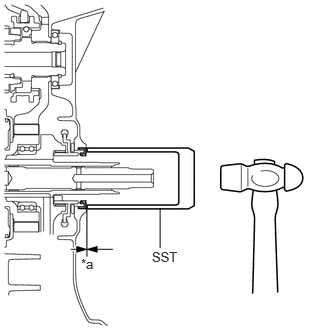
| *a | Depth |
Using SST and a hammer, drive the transaxle housing type T oil seal in evenly, until it is even with the side surface of the oil pump housing.
- Standard Depth:
-0.5 to 0.5 mm (-0.0197 to 0.0197 in.)
- NOTICE:
- ·
Drive the transaxle housing type T oil seal in gradually, while visually checking that it is even.
·After installation, confirm that the transaxle housing type T oil seal has been driven in until it is even with the side surface of the oil pump housing.
·Wipe any extra grease off with your hand.
32000A
10.INSTALL TORQUE CONVERTER ASSEMBLY
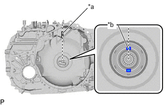
| *a | Matchmark |
| *b | Key |
Set the key at the top of the drive sprocket and put a matchmark on the transaxle housing.
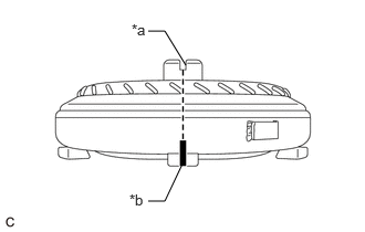
| *a | Groove |
| *b | Matchmark |
Place a matchmark on the torque converter assembly so that the position of its groove is clearly indicated.
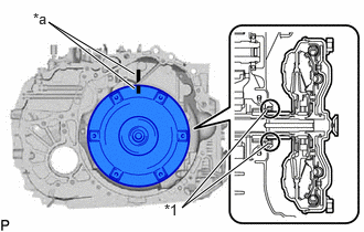
| *1 | Transaxle Housing Type T Oil Seal |
| *a | Matchmark |
Align the matchmark on the transaxle housing with the one on the torque converter assembly and engage the splines of the input shaft with the turbine runner splines.
- NOTICE:
- ·
Install the torque converter assembly to the input shaft while keeping it horizontal.
·Do not damage the transaxle housing type T oil seal.

| *1 | Transaxle Housing Type T Oil Seal |
| *a | Matchmark |
Rotate the torque converter assembly approximately 180° and engage the splines of the stator shaft with the stator assembly.
- NOTICE:
- ·
Install the torque converter assembly to the input shaft while keeping it horizontal.
·Do not push the torque converter assembly excessively when rotating it.
·Do not damage the transaxle housing type T oil seal.
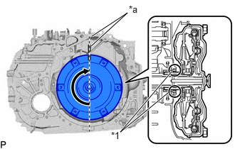
| *1 | Transaxle Housing Type T Oil Seal |
| *a | Matchmark |
Rotate the torque converter assembly approximately 180° again, align the matchmark on the torque converter assembly with the one on the transaxle housing and insert the groove of the torque converter assembly into the key of the drive sprocket.
- NOTICE:
- ·
Install the torque converter assembly to the input shaft while keeping it horizontal.
·Do not push the torque converter assembly excessively when rotating it.
·Do not damage the transaxle housing type T oil seal.
Clean the drive plate and torque converter setting bolt holes.
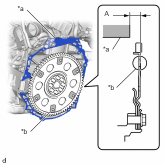
| *a | Engine Assembly Surface |
| *b | Drive Plate Surface |
Using a vernier caliper and straightedge, measure the dimension (A) between the continuously variable transaxle assembly contact surface of the engine*a and the torque converter assembly contact surfaces of the drive plate*b.
- NOTICE:
-
Make sure to deduct the thickness of the straightedge.
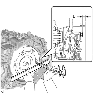
Using a vernier caliper and straightedge, measure the dimension (B) shown in the illustration and check that the dimension (B) is more than the dimension (A), which was measured in the previous step.
- Standard:
B = A + 1 mm (0.0394 in.) or more
- NOTICE:
- ·
Make sure to deduct the thickness of the straightedge.
·If the continuously variable transaxle assembly is installed to the engine assembly with the torque converter assembly not sufficiently inserted, the torque converter assembly may be damaged.
·Do not include the thickness of the set block.
30400
11.INSTALL CONTINUOUSLY VARIABLE TRANSAXLE ASSEMBLY
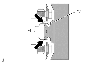
| *1 | Crankshaft |
| *2 | Torque Converter Assembly Centerpiece |
|
|
Clutch Spline Grease |
Apply clutch spline grease to the surface of the crankshaft that contacts the torque converter assembly centerpiece.
- Clutch Spline Grease:
Toyota Genuine Clutch Spline Grease or equivalent
- Maximum Grease Amount:
Approximately 1 g (0.0353 oz)
|
|
Bolt A |
|
|
Bolt B |

|
Bolt C |

|
Knock Pin |
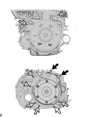
Confirm that the 2 knock pins are installed to the engine assembly and are not damaged.
While keeping the engine assembly and continuously variable transaxle assembly horizontal, align the knock pins with the holes in the continuously variable assembly and install the continuously variable assembly with the 8 bolts shown in the illustration.
- Torque:
- for bolt A : 64 N*m (653 kgf*cm, 47 ft.*lbf)
- for bolt B : 25 N*m (255 kgf*cm, 18 ft.*lbf)
- for bolt C : 46 N*m (469 kgf*cm, 34 ft.*lbf)
- Bolt Length:
Bolt Length A 50 mm (1.97 in.) B 35 mm (1.38 in.) C 45 mm (1.77 in.)
- NOTICE:
- ·
Make sure that the wire harness or similar items are not pinched between the contact surfaces.
·Do not use excess force when installing the continuously variable transaxle assembly.
·When mounting the continuously variable transaxle assembly to the engine assembly, make sure to securely fit the knock pins into the knock holes.
·Check that the torque converter assembly rotates.
·When tightening the bolts, be sure that the mating surfaces of the engine assembly and the continuously variable transaxle assembly are in close contact with one another.
- HINT:
- ·
Bolt (A), (B): Install from continuously variable transaxle assembly side.
·Bolt (C): Install from engine assembly side.
12303
12.INSTALL REAR ENGINE MOUNTING BRACKET SUB-ASSEMBLY
Install the No. 2 rear engine mounting bracket to the rear engine mounting bracket with the 2 bolts.
- Torque:
- 42 N*m (428 kgf*cm, 31 ft.*lbf)
|
|
Bolt A |
|
|
Bolt B |
|
|
Bolt C |
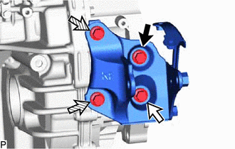
Install the rear engine mounting bracket sub-assembly to the continuously variable transaxle with the 4 bolts.
- Torque:
- 42 N*m (428 kgf*cm, 31 ft.*lbf)
- HINT:
-
Tightening order: Temporarily install bolt (A) → Tighten bolt (B) → Tighten bolt (A) → Tighten bolt (C)
12371A
13.INSTALL REAR ENGINE MOUNTING INSULATOR
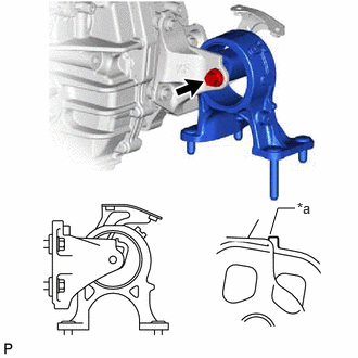
| *a | Rubber Protrusion |
Install the rear engine mounting insulator to the rear engine mounting bracket sub-assembly with the bolt.
- Torque:
- 72 N*m (734 kgf*cm, 53 ft.*lbf)
- NOTICE:
-
Align the rubber protrusion of the rear engine mounting insulator with the shape of the rear engine mounting bracket sub-assembly.
|
|
Bolt A |
|
|
Bolt B |
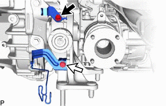
Install the 2 wire harness clamp brackets to the rear engine mounting insulator with the 2 bolts.
- Torque:
- for bolt A : 10 N*m (102 kgf*cm, 7 ft.*lbf)
- for bolt B : 13 N*m (133 kgf*cm, 10 ft.*lbf)
11363A
14.INSTALL FLYWHEEL HOUSING SIDE COVER
28100
15.INSTALL STARTER ASSEMBLY
12311A
16.INSTALL TRANSVERSE ENGINE ENGINE MOUNTING BRACKET
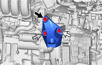
|
|
Bolt A |
|
|
Bolt B |
|
|
Bolt C |
Install the transverse engine engine mounting bracket to the continuously variable transaxle assembly with the 3 bolts.
- Torque:
- 42 N*m (428 kgf*cm, 31 ft.*lbf)
- HINT:
-
Tightening order: Temporarily install bolt (A) → Tighten bolt (B) → Tighten bolt (C) → Tighten bolt (A)
12361
17.INSTALL FRONT ENGINE MOUNTING INSULATOR
Install the front engine mounting insulator to the transverse engine engine mounting bracket with the bolt.
- Torque:
- 72 N*m (734 kgf*cm, 53 ft.*lbf)
37117
18.INSTALL PROPELLER SHAFT HEAT INSULATOR
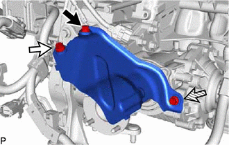
|
|
Bolt A |
|
|
Bolt B |
|
|
Bolt C |
Install the propeller shaft heat insulator to the continuously variable transaxle assembly with the 3 bolts.
- Torque:
- 18 N*m (184 kgf*cm, 13 ft.*lbf)
- HINT:
-
Tightening order: Temporarily install bolt (A) → Tighten install bolt (B) → Tighten bolt (C) → Tighten bolt (B) → Tighten bolt (A)
33493C
19.INSTALL TRANSMISSION OIL COOLER
32941R
20.CONNECT OIL COOLER INLET HOSE
32942N
21.CONNECT NO. 1 OIL COOLER OUTLET HOSE
22.INSTALL WATER BY-PASS PIPE SUB-ASSEMBLY
Install the water by-pass pipe sub-assembly to the continuously variable transaxle assembly with the 3 bolts.
- Torque:
- 10 N*m (102 kgf*cm, 7 ft.*lbf)
Connect the No. 3 water by-pass hose and No. 4 water by-pass hose to the water by-pass pipe sub-assembly, and slide the 2 hose clips to secure the hoses.
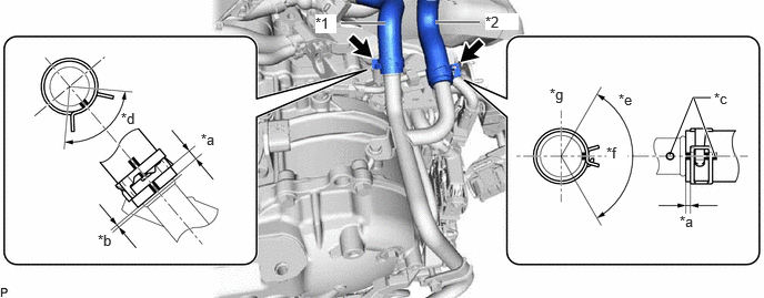
| *1 | No. 3 Water By-pass Hose | *2 | No. 4 Water By-pass Hose |
| *a | 2 to 7 mm (0.0787 to 0.275 in.) | *b | 0 to 3 mm (0 to 0.118 in.) |
| *c | Paint Mark (Rear Side of Vehicle) | *d | 90° (Claw of Hose Clip Location) |
| *e | 120° (Claw of Hose Clip Location) | *f | RR Side |
| *g | Upper Side | - | - |
- NOTICE:
- ·
Make sure to slide the No. 3 water by-pass hose and No. 4 water by-pass hose until they contact the hose stopper of the transmission oil cooler.
·Align the hose paint mark with the position shown in the illustration.
·Make sure that the claws of the hose clip are within the location shown in the illustration.
16264D
23.INSTALL NO. 2 WATER BY-PASS HOSE
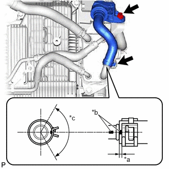
| *a | 2 to 7 mm (0.0787 to 0.2756 in.) |
| *b | Paint Mark (LH Side of Vehicle) |
| *c | 120° (Claw of Hose Clip Location) |
Connect the No. 2 water by-pass hose to the transmission oil cooler and slide the hose clip to secure the hose.
- NOTICE:
- ·
Make sure to slide the No. 2 water by-pass hose until it contacts the hose stopper of the transmission oil cooler.
·Align the hose paint mark with the position shown in the illustration.
·Make sure that the claws of the hose clip are within the location shown in the illustration.
Install the No. 2 water by-pass hose to the water hose clamp bracket with the bolt.
- Torque:
- 19 N*m (194 kgf*cm, 14 ft.*lbf)
16261G
24.CONNECT NO. 1 WATER BY-PASS HOSE
Attach the 2 clamps.
Connect the No. 1 water by-pass hose to the transmission oil cooler and slide the hose clip to secure the hose.
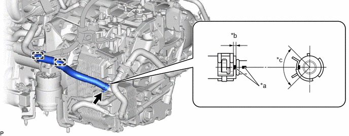
| *a | Paint Mark (Upper Side of Vehicle) | *b | 2 to 7 mm (0.0787 to 0.275 in.) |
| *c | 120° (Claw of Hose Clip Location) | - | - |
- NOTICE:
- ·
Make sure to slide the No. 1 water by-pass hose until it contacts the hose stopper of the transmission oil cooler.
·Make sure to align the paint mark of the No. 1 water by-pass hose with the paint mark of the transmission oil cooler.
·Make sure that the claws of the hose clip are within the location shown in the illustration.
82121
25.CONNECT ENGINE WIRE
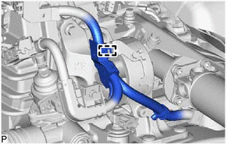
Attach the clamp to connect the engine wire.
Attach the 5 clamps to connect the engine wire to the continuously variable transaxle assembly.
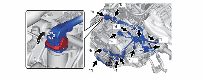
| *a | Transmission Wire Connector | *b | Shift Stroke Sensor Connector |
| *c | Shift Lever Position Sensor Connector | *d | Transmission Revolution Sensor (NOUT) Connector |
| *e | Transmission Revolution Sensor (NSS) Connector | *f | Oil Pressure Sensor Connector |
| *g | Transmission Revolution Sensor (NT) Connector | *h | Oil Pump With Motor Assembly Connector |
| *i | Transfer sensor connector | - | - |

|
Install in this Direction | - | - |
Install the 3 bolts to connect the engine wire to the continuously variable transaxle assembly.
- Torque:
- 10 N*m (102 kgf*cm, 7 ft.*lbf)
for Transfer (GF2A):
Connect the transfer sensor connector.
Connect the oil pump with motor assembly connector.
Connect the transmission revolution sensor (NT) connector.
Connect the oil pressure sensor connector.
Connect the transmission revolution sensor (NSS) connector.
Connect the transmission revolution sensor (NOUT) connector.
Connect the shift lever position sensor connector.
Connect the shift stroke sensor connector.
Connect the transmission wire connector and rotate the lever and attach the claw.
- HINT:
-
Rotate the lever until the claw of the transmission wire connector makes a click sound.
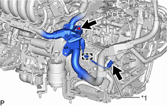
| *1 | Flow Shutting Valve (Water Valve) Connector |
Attach the clamp to connect the engine wire.
Connect the engine wire to the continuously variable transaxle assembly with the bolt.
- Torque:
- 10 N*m (102 kgf*cm, 7 ft.*lbf)
Connect the flow shutting valve (water valve) connector.
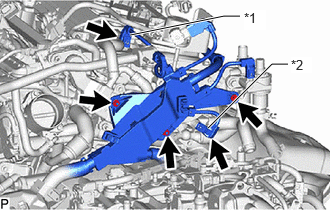
| *1 | Camshaft Position Sensor Connector |
| *2 | Engine Coolant Temperature Sensor Connector |
Connect the engine coolant temperature sensor connector.
Connect the camshaft position sensor connector.
Connect the engine wire to the engine assembly with the bolt and 2 nuts.
- Torque:
- 10 N*m (102 kgf*cm, 7 ft.*lbf)
51100H
26.INSTALL FRONT ENGINE SUPPORT MEMBER SUB-ASSEMBLY
27.CONNECT WIRE HARNESS
45319
28.INSTALL STEERING GEAR HEAT INSULATOR
29.REMOVE ENGINE HANGERS
23825A
30.INSTALL FUEL DELIVERY GUARD
32101G
31.INSTALL DRIVE PLATE AND TORQUE CONVERTER SETTING BOLT
Clean the threads of the 6 drive plate and torque converter setting bolts.
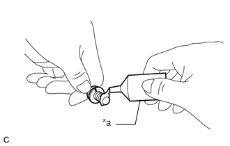
| *a | Adhesive |
Apply a few drops of adhesive to 2 or 3 threads at the tip of each of the 6 drive plate and torque converter setting bolts.
- Adhesive:
Toyota Genuine Adhesive 1324, Three Bond 1324 or equivalent
- NOTICE:
-
In order to ensure proper installation of the 6 drive plate and torque converter setting bolts, apply adhesive to the 6 drive plate and torque converter setting bolts and install them within 10 minutes of adhesive application.
Turn the crankshaft to gain access to the installation locations of the 6 drive plate and torque converter setting bolts and install each drive plate and torque converter setting bolt while holding the crankshaft pulley bolt with a wrench.
- Torque:
- 41 N*m (418 kgf*cm, 30 ft.*lbf)
- NOTICE:
-
First install the black colored drive plate and torque converter setting bolt, and then the remaining 5 silver colored drive plate and torque converter setting bolts.
11361J
32.INSTALL FLYWHEEL HOUSING UNDER COVER
17141
33.INSTALL EXHAUST MANIFOLD
34.INSTALL ENGINE ASSEMBLY WITH TRANSAXLE