LIGHTING (EXT) HEADLIGHT ASSEMBLY(for Triple Beam Headlight) REMOVAL
CAUTION / NOTICE / HINT
The necessary procedures (adjustment, calibration, initialization or registration) that must be performed after parts are installed, removed or replaced during the headlight assembly removal/installation are shown below.
| Replaced Part or Performed Procedure | Necessary Procedures | Effect/Inoperative Function when Necessary Procedures are not Performed | Link |
|---|---|---|---|
| Front bumper assembly (Including removal and installation) | Front television camera view adjustment | Panoramic view monitor system | ( 202304,999999,_56,_083082,_0586733,RM1000000029R9F,) 202304,999999,_56,_083082,_0586733,RM1000000029R9F,)
|
| Replaced Part or Performed Procedure | Necessary Procedures | Effect/Inoperative Function when Necessary Procedures are not Performed | Link |
|---|---|---|---|
| Front bumper assembly (Including removal and installation) | Front television camera view adjustment | Panoramic view monitor system | (202304,999999,_56,_083082,_0586733,RM1000000029R9F,)
|
- HINT:
- ·
Use the same procedure for the RH and LH sides.
·The procedure listed below is for the LH side.
PROCEDURE

 1.REMOVE FRONT BUMPER ASSEMBLY
for Type A: Click hereVehicle Exterior>EXTERIOR PANELS / TRIM>FRONT BUMPER (for Type A)>REMOVAL202304,999999,_59,_083111,_0400751,RM1000000029RQQ,
for Type B: Click hereVehicle Exterior>EXTERIOR PANELS / TRIM>FRONT BUMPER (for Type B)>REMOVAL202304,999999,_59,_083111,_0417477,RM1000000029RQU,
for Off Road Package: Click hereVehicle Exterior>EXTERIOR PANELS / TRIM>FRONT BUMPER (for Off Road Package)>REMOVAL202304,999999,_59,_083111,_0587172,RM1000000029SJZ,
2.REMOVE HEADLIGHT ASSEMBLY LH (for Type A)
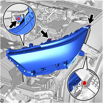

|
Screw |

|
Bolt |

|
Protective Tape |
Apply protective tape as shown in the illustration.
Remove the 3 screws and bolt.
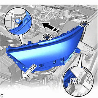
| *a | Lower Bracket |

|
Place Hands Here |

|
Remove in this Direction (1) |

|
Remove in this Direction (2) |
Place your hands at the positions shown in the illustration and disconnect the 2 brackets of the headlight assembly LH from the screw seats.
- NOTICE:
-
Be careful not to break the bracket.
Slide the headlight assembly LH in the direction indicated by the arrow (1) and detach the guide and lower bracket.
Slide the headlight assembly LH in the direction indicated by the arrow (2) and remove it.
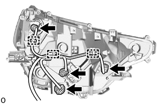
Disconnect the 4 connectors.
Detach the clamp.
3.REMOVE HEADLIGHT ASSEMBLY LH (for Type B)
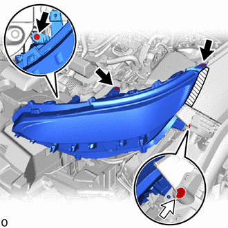
|
|
Screw |
|
|
Bolt |
|
|
Protective Tape |
Apply protective tape as shown in the illustration.
Remove the 3 screws and bolt.
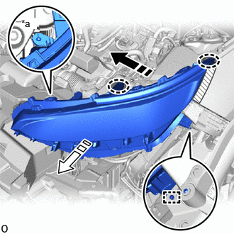
| *a | Lower Bracket |
|
|
Place Hands Here |
|
|
Remove in this Direction (1) |
|
|
Remove in this Direction (2) |
Place your hands at the positions shown in the illustration and disconnect the 2 brackets of the headlight assembly LH from the screw seats.
- NOTICE:
-
Be careful not to break the bracket.
Slide the headlight assembly LH in the direction indicated by the arrow (1) and detach the guide and lower bracket.
Slide the headlight assembly LH in the direction indicated by the arrow (2) and remove it.
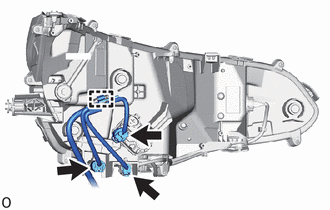
Disconnect the 3 connectors.
Detach the clamp.