HEATING / AIR CONDITIONING CONDENSER(for Gasoline Model) REMOVAL
CAUTION / NOTICE / HINT
The necessary procedures (adjustment, calibration, initialization or registration) that must be performed after parts are removed and installed, or replaced during cooler condenser assembly removal/installation are shown below.
| Replaced Part or Performed Procedure | Necessary Procedures | Effect/Inoperative Function when Necessary Procedures are not Performed | Link |
|---|---|---|---|
| Front bumper assembly (Including removal and installation) | Front television camera view adjustment | Panoramic view monitor system | ( 202304,999999,_56,_083082,_0586733,RM1000000029R9F,) 202304,999999,_56,_083082,_0586733,RM1000000029R9F,)
|
·
Front television camera assembly, radiator grille assembly or front bumper assembly ·
Rear television camera assembly ·
Side television camera assembly LH or outer rear view mirror assembly LH ·
Side television camera assembly RH or outer rear view mirror assembly RH |
Television camera view adjustment (Adjustment of all cameras)
|
Panoramic view monitor system | (202304,999999,_56,_083082,_0586733,RM1000000029R9F,)
|
PROCEDURE

 1.RECOVER REFRIGERANT FROM REFRIGERATION SYSTEM
2.REMOVE FRONT BUMPER ASSEMBLY
86520
3.REMOVE LOW PITCHED HORN ASSEMBLY
88710E
4.DISCONNECT AIR CONDITIONING TUBE AND ACCESSORY ASSEMBLY
Press the air conditioning tube and accessory assembly to the cooler condenser assembly, and then release the piping clamp lock.
- NOTICE:
-
Do not apply excessive force to the air conditioning tube and accessory assembly.
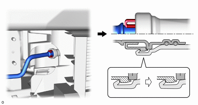
| *1 | Air Conditioning Tube and Accessory Assembly | *2 | Cooler Condenser Assembly |
| *3 | Piping Clamp | - | - |
| *a | Press In | - | - |
While releasing the piping clamp lock, use pliers or another tool to pinch near the rear end of the piping clamp, and then disconnect the air conditioning tube and accessory assembly as you buckle it.
- NOTICE:
- ·
If any foreign matter is attached to the connecting parts, brush it off or use compressed air to remove it before disconnecting the parts.
·Make sure that fragments of the piping clamp do not enter the piping.
·When the piping clamp is buckled, cracks form. Therefore, make sure to replace it with a new one.
·Remove any foreign matter from the connecting parts of the air conditioning tube and accessory assembly and cooler condenser assembly.
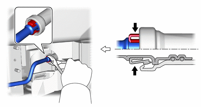
| *1 | Air Conditioning Tube and Accessory Assembly | *2 | Cooler Condenser Assembly |
| *3 | Piping Clamp | - | - |
| *a | Buckle | *b | Pull Out |
Remove the 2 O-rings from the air conditioning tube and accessory assembly.
- NOTICE:
-
Seal the openings of the disconnected parts with vinyl tape to prevent entry of moisture and foreign matter.
Remove the piping clamp.
88711
5.DISCONNECT NO. 1 COOLER REFRIGERANT DISCHARGE HOSE
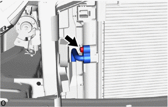
Remove the bolt and disconnect the No. 1 cooler refrigerant discharge hose.
- NOTICE:
-
Do not apply excessive force to the No. 1 cooler refrigerant discharge hose.
Remove the O-ring from the No. 1 cooler refrigerant discharge hose.
- NOTICE:
-
Seal the openings of the disconnected parts using vinyl tape to prevent entry of moisture and foreign matter.
53630
6.DISCONNECT HOOD LOCK CONTROL CABLE ASSEMBLY
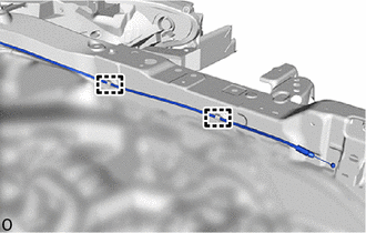
Disconnect the hood lock control cable assembly from the clamp.
53205
7.REMOVE UPPER RADIATOR SUPPORT SUB-ASSEMBLY
w/ Engine Hood Courtesy Switch
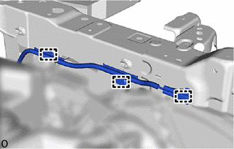
Detach the clamp.
Detach the clamp.
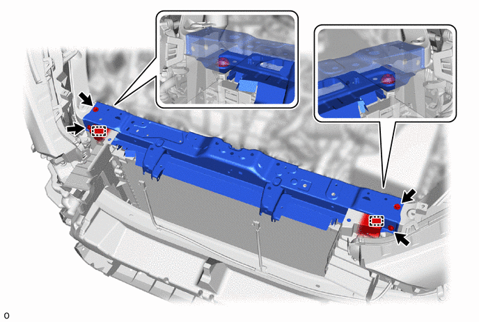
| *1 | Radiator Support Cushion | - | - |
Remove the 4 bolts.
Detach the 2 radiator support cushions and remove the upper radiator support sub-assembly.
- NOTICE:
-
Do not damage the cooler condenser assembly or radiator assembly when removing the upper radiator support sub-assembly.
884A0
8.REMOVE COOLER CONDENSER ASSEMBLY
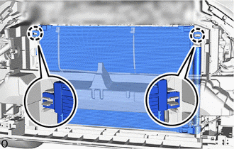
Detach the claw.
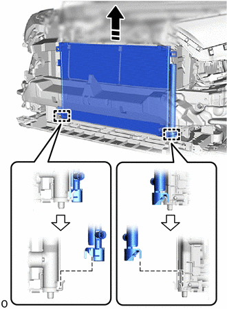

|
Remove in this Direction |
Detach the guide and remove the cooler condenser assembly as shown in the illustration.
- NOTICE:
-
Do not damage the cooler condenser assembly or radiator assembly when removing the cooler condenser assembly.