RM36D0EC _56 Audio / Visual / Telematics _083082 PARK ASSIST / MONITORING _0586733 PANORAMIC VIEW MONITOR SYSTEM C

PARK ASSIST / MONITORING  PANORAMIC VIEW MONITOR SYSTEM  C168811  Camera Power Supply Circuit Short to Ground  C168812  Camera Power Supply Circuit Short to Battery  


DESCRIPTION

This DTC is output when the self diagnostic function of the parking assist ECU detects an abnormal value of the power supply voltage supplied to the rear/front/side camera LH/side camera RH.

DTC No. Detection Item DTC Detection Condition Trouble Area DTC Output from Priority
C168811 Camera Power Supply Circuit Short to Ground Camera power supply voltage value abnormal (less than lower limit)
·

Harness or connector

·

Parking assist ECU

·

Front television camera assembly

·

Rear television camera assembly

·

Side television camera assembly LH

·

Side television camera assembly RH


Circumference Monitoring Camera Control Module A
C168812 Camera Power Supply Circuit Short to Battery Camera power supply voltage value abnormal (higher than upper limit)
·

Harness or connector

·

Parking assist ECU

·

Front television camera assembly

·

Rear television camera assembly

·

Side television camera assembly LH

·

Side television camera assembly RH


Circumference Monitoring Camera Control Module A

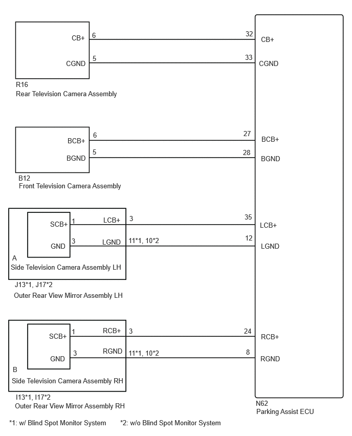
WIRING DIAGRAM

for SFTM Made:
E424821E27
0.323,1.823 2.813,2.063 2.49,0.24 10 false Rear Television Camera Assembly 1.344,1.208 1.792,1.365 0.448,0.156 10 false CGND 1.458,0.688 1.76,0.865 0.302,0.177 10 false CB+ 1.875,0.635 2.083,0.802 0.208,0.167 10 false 6 1.885,1.104 2.094,1.271 0.208,0.167 10 false 5 5,0.604 5.208,0.771 0.208,0.167 10 false 32 5.313,0.719 5.698,0.906 0.385,0.188 10 false CB+ 4.99,1.083 5.198,1.25 0.208,0.167 10 false 33 5.271,1.208 5.698,1.385 0.427,0.177 10 false CGND 0.385,3.698 2.656,4.146 2.271,0.448 10 false Front Television Camera Assembly 0.375,3.542 0.781,3.719 0.406,0.177 10 false B12 1.375,2.781 1.802,2.958 0.427,0.177 10 false BCB+ 1.354,3.135 1.781,3.313 0.427,0.177 10 false BGND 1.896,2.667 2.104,2.833 0.208,0.167 10 false 6 1.885,3.01 2.094,3.177 0.208,0.167 10 false 5 4.958,2.635 5.167,2.802 0.208,0.167 10 false 27 5.323,2.75 5.75,2.927 0.427,0.177 10 false BCB+ 5.313,3.146 5.74,3.323 0.427,0.177 10 false BGND 4.948,3.021 5.156,3.188 0.208,0.167 10 false 28 0.24,7.667 2.771,7.948 2.531,0.281 10 false Side Television Camera Assembly RH 0.302,5.708 1.74,5.938 1.438,0.229 10 false J13*1, J17*2 0.302,8.177 2.688,8.354 2.385,0.177 10 false Outer Rear View Mirror Assembly RH 2.094,6.646 2.521,6.823 0.427,0.177 10 false RCB+ 2.094,7.063 2.521,7.24 0.427,0.177 10 false RGND 2.635,4.365 3.302,4.542 0.667,0.177 10 false 3 2.615,4.813 3.563,5.042 0.948,0.229 10 false 11*1, 10*2 5.313,6.771 5.74,6.948 0.427,0.177 10 false RCB+ 4.979,4.333 5.188,4.5 0.208,0.167 10 false 35 5.302,7.219 5.729,7.396 0.427,0.177 10 false RGND 4.99,4.76 5.198,4.927 0.208,0.167 10 false 12 0.219,5.354 2.938,5.583 2.719,0.229 10 false Side Television Camera Assembly LH 0.323,8 1.167,8.177 0.844,0.177 10 false I13*1, I17*2 0.281,5.927 2.667,6.104 2.385,0.177 10 false Outer Rear View Mirror Assembly LH 5.292,4.5 5.719,4.677 0.427,0.177 10 false LCB+ 4.969,6.656 5.177,6.823 0.208,0.167 10 false 24 5.313,4.927 5.74,5.104 0.427,0.177 10 false LGND 5.01,7.083 5.219,7.25 0.208,0.167 10 false 8 5.208,8.125 5.677,8.292 0.469,0.167 10 false N62 5.219,8.292 6.5,8.479 1.281,0.188 10 false Parking Assist ECU 2.625,6.656 3.292,6.833 0.667,0.177 10 false 3 2.615,7.104 3.49,7.302 0.875,0.198 10 false 11*1, 10*2 2.104,4.396 2.531,4.573 0.427,0.177 10 false LCB+ 2.083,4.844 2.51,5.021 0.427,0.177 10 false LGND 0.323,1.635 0.677,1.865 0.354,0.229 10 false R16 0.25,5.167 0.99,5.344 0.74,0.177 10 false A 1,6.76 1.427,6.938 0.427,0.177 10 false SCB+ 1.021,7.219 1.448,7.396 0.427,0.177 10 false GND 1.458,6.667 2.125,6.844 0.667,0.177 10 false 1 1.49,7.104 2.156,7.281 0.667,0.177 10 false 3 0.26,7.438 1,7.615 0.74,0.177 10 false B 1.031,4.927 1.458,5.104 0.427,0.177 10 false GND 1.021,4.479 1.448,4.656 0.427,0.177 10 false SCB+ 1.458,4.417 2.125,4.594 0.667,0.177 10 false 1 1.458,4.823 2.125,5 0.667,0.177 10 false 3 0.188,8.521 2.688,8.865 2.5,0.344 10 false *1: w/ Blind Spot Monitor System 2.448,8.521 4.948,8.865 2.5,0.344 10 false *2: w/o Blind Spot Monitor System

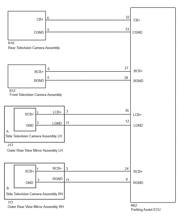
for GTMC Made:
E424821E28
0.323,1.823 2.813,2.063 2.49,0.24 10 false Rear Television Camera Assembly 1.344,1.208 1.792,1.365 0.448,0.156 10 false CGND 1.458,0.688 1.76,0.865 0.302,0.177 10 false CB+ 1.875,0.635 2.083,0.802 0.208,0.167 10 false 6 1.885,1.104 2.094,1.271 0.208,0.167 10 false 5 5,0.604 5.208,0.771 0.208,0.167 10 false 32 5.313,0.719 5.698,0.906 0.385,0.188 10 false CB+ 4.99,1.083 5.198,1.25 0.208,0.167 10 false 33 5.271,1.208 5.698,1.385 0.427,0.177 10 false CGND 0.385,3.698 2.656,4.146 2.271,0.448 10 false Front Television Camera Assembly 0.375,3.542 0.781,3.719 0.406,0.177 10 false B12 1.375,2.781 1.802,2.958 0.427,0.177 10 false BCB+ 1.354,3.135 1.781,3.313 0.427,0.177 10 false BGND 1.896,2.667 2.104,2.833 0.208,0.167 10 false 6 1.885,3.01 2.094,3.177 0.208,0.167 10 false 5 4.958,2.635 5.167,2.802 0.208,0.167 10 false 27 5.323,2.75 5.75,2.927 0.427,0.177 10 false BCB+ 5.313,3.146 5.74,3.323 0.427,0.177 10 false BGND 4.948,3.021 5.156,3.188 0.208,0.167 10 false 28 0.24,7.667 2.771,7.948 2.531,0.281 10 false Side Television Camera Assembly RH 0.302,5.708 1.74,5.938 1.438,0.229 10 false J13 0.302,8.177 2.688,8.354 2.385,0.177 10 false Outer Rear View Mirror Assembly RH 2.094,6.646 2.521,6.823 0.427,0.177 10 false RCB+ 2.094,7.063 2.521,7.24 0.427,0.177 10 false RGND 2.635,4.365 3.302,4.542 0.667,0.177 10 false 3 2.615,4.823 3.563,5.052 0.948,0.229 10 false 11 5.313,6.771 5.74,6.948 0.427,0.177 10 false RCB+ 4.979,4.333 5.188,4.5 0.208,0.167 10 false 35 5.302,7.219 5.729,7.396 0.427,0.177 10 false RGND 4.99,4.76 5.198,4.927 0.208,0.167 10 false 12 0.219,5.354 2.938,5.583 2.719,0.229 10 false Side Television Camera Assembly LH 0.323,8 1.167,8.177 0.844,0.177 10 false I13 0.281,5.927 2.667,6.104 2.385,0.177 10 false Outer Rear View Mirror Assembly LH 5.292,4.5 5.719,4.677 0.427,0.177 10 false LCB+ 4.969,6.656 5.177,6.823 0.208,0.167 10 false 24 5.313,4.927 5.74,5.104 0.427,0.177 10 false LGND 5.01,7.083 5.219,7.25 0.208,0.167 10 false 8 5.208,8.125 5.677,8.292 0.469,0.167 10 false N62 5.219,8.292 6.5,8.479 1.281,0.188 10 false Parking Assist ECU 2.625,6.656 3.292,6.833 0.667,0.177 10 false 3 2.615,7.104 3.49,7.302 0.875,0.198 10 false 11 2.104,4.396 2.531,4.573 0.427,0.177 10 false LCB+ 2.083,4.844 2.51,5.021 0.427,0.177 10 false LGND 0.323,1.635 0.677,1.865 0.354,0.229 10 false R16 0.25,5.167 0.99,5.344 0.74,0.177 10 false A 1,6.76 1.427,6.938 0.427,0.177 10 false SCB+ 1.021,7.219 1.448,7.396 0.427,0.177 10 false GND 1.458,6.667 2.125,6.844 0.667,0.177 10 false 1 1.49,7.104 2.156,7.281 0.667,0.177 10 false 3 0.26,7.438 1,7.615 0.74,0.177 10 false B 1.031,4.927 1.458,5.104 0.427,0.177 10 false GND 0.99,4.479 1.417,4.656 0.427,0.177 10 false SCB+ 1.458,4.417 2.125,4.594 0.667,0.177 10 false 1 1.458,4.823 2.125,5 0.667,0.177 10 false 3

CAUTION / NOTICE / HINT

NOTICE:

Depending on the parts that are replaced or operations that are performed during vehicle inspection or maintenance, calibration of other systems as well as the panoramic view monitor system may be needed.

Click hereAudio / Visual / Telematics>PARK ASSIST / MONITORING>PANORAMIC VIEW MONITOR SYSTEM>CALIBRATION


PROCEDURE

1.CHECK HARNESS AND CONNECTOR (PARKING ASSIST ECU - REAR TELEVISION CAMERA ASSEMBLY)
a.

Disconnect the N62 parking assist ECU connector.


b.

Disconnect the R16 rear television camera assembly connector.


c.

Measure the resistance according to the value(s) in the table below.

Standard Resistance:
Tester Connection Condition Specified Condition
N62-32 (CB+) - R16-6 (CB+) Always Below 1 Ω
N62-33 (CGND) - R16-5 (CGND) Always Below 1 Ω
N62-32 (CB+) or R16-6 (CB+) - Body ground Always 10 kΩ or higher
N62-33 (CGND) or R16-5 (CGND) - Body ground Always 10 kΩ or higher


Result:
Proceed to
OK
NG


OK

2.CHECK HARNESS AND CONNECTOR (PARKING ASSIST ECU - FRONT TELEVISION CAMERA ASSEMBLY)

NG

REPAIR OR REPLACE HARNESS OR CONNECTOR

2.CHECK HARNESS AND CONNECTOR (PARKING ASSIST ECU - FRONT TELEVISION CAMERA ASSEMBLY)
a.

Disconnect the N62 parking assist ECU connector.


b.

Disconnect the B12 front television camera assembly connector.


c.

Measure the resistance according to the value(s) in the table below.

Standard Resistance:
Tester Connection Condition Specified Condition
N62-27 (BCB+) - B12-6 (BCB+) Always Below 1 Ω
N62-28 (BGND) - B12-5 (BGND) Always Below 1 Ω
N62-27 (BCB+) or B12-6 (BCB+) - Body ground Always 10 kΩ or higher
N62-28 (BGND) or B12-5 (BGND) - Body ground Always 10 kΩ or higher


Result:
Proceed to
OK
NG


OK

3.CHECK HARNESS AND CONNECTOR (PARKING ASSIST ECU - OUTER REAR VIEW MIRROR ASSEMBLY RH)

NG

REPAIR OR REPLACE HARNESS OR CONNECTOR

3.CHECK HARNESS AND CONNECTOR (PARKING ASSIST ECU - OUTER REAR VIEW MIRROR ASSEMBLY RH)
a.

Disconnect the N62 parking assist ECU connector.


b.

Disconnect the I13*1 or I17*2 outer rear view mirror assembly RH connector.

*1: for SFTM Made with Blind Spot Monitor System, for GTMC Made

*2: for SFTM Made without Blind Spot Monitor System


c.

Measure the resistance according to the value(s) in the table below.

Standard Resistance:
for SFTM Made with Blind Spot Monitor System, for GTMC Made:
Tester Connection Condition Specified Condition
N62-24 (RCB+) - I13-3 (RCB+) Always Below 1 Ω
N62-8 (RGND) - I13-11 (RGND) Always Below 1 Ω
N62-24 (RCB+) or I13-3 (RCB+) - Body ground Always 10 kΩ or higher
N62-8 (RGND) or I13-11 (RGND) - Body ground Always 10 kΩ or higher

for SFTM Made without Blind Spot Monitor System:
Tester Connection Condition Specified Condition
N62-24 (RCB+) - I17-3 (RCB+) Always Below 1 Ω
N62-8 (RGND) - I17-10 (RGND) Always Below 1 Ω
N62-24 (RCB+) or I17-3 (RCB+) - Body ground Always 10 kΩ or higher
N62-8 (RGND) or I17-10 (RGND) - Body ground Always 10 kΩ or higher


Result:
Proceed to
OK
NG


OK

4.CHECK HARNESS AND CONNECTOR (PARKING ASSIST ECU - OUTER REAR VIEW MIRROR ASSEMBLY LH)

NG

REPAIR OR REPLACE HARNESS OR CONNECTOR

4.CHECK HARNESS AND CONNECTOR (PARKING ASSIST ECU - OUTER REAR VIEW MIRROR ASSEMBLY LH)
a.

Disconnect the N62 parking assist ECU connector.


b.

Disconnect the J13*1 or J17*2 outer rear view mirror assembly LH connector.

*1: for SFTM Made with Blind Spot Monitor System, for GTMC Made

*3: for SFTM Made without Blind Spot Monitor System


c.

Measure the resistance according to the value(s) in the table below.

Standard Resistance:
for SFTM Made with Blind Spot Monitor System, for GTMC Made:
Tester Connection Condition Specified Condition
N62-35 (LCB+) - J13-3 (LCB+) Always Below 1 Ω
N62-12 (LGND) - J13-11 (LGND) Always Below 1 Ω
N62-35 (LCB+) or J13-3 (LCB+) - Body ground Always 10 kΩ or higher
N62-12 (LGND) or J13-11 (LGND) - Body ground Always 10 kΩ or higher

for SFTM Made without Blind Spot Monitor System:
Tester Connection Condition Specified Condition
N62-35 (LCB+) - J17-3 (LCB+) Always Below 1 Ω
N62-12 (LGND) - J17-10 (LGND) Always Below 1 Ω
N62-35 (LCB+) or J17-3 (LCB+) - Body ground Always 10 kΩ or higher
N62-12 (LGND) or J17-10 (LGND) - Body ground Always 10 kΩ or higher


Result:
Proceed to
OK
NG


OK

5.CHECK PARKING ASSIST ECU

NG

REPAIR OR REPLACE HARNESS OR CONNECTOR

5.CHECK PARKING ASSIST ECU
a.
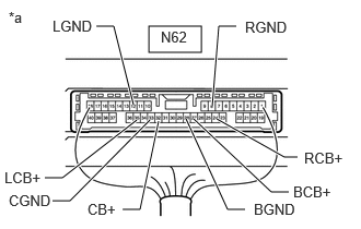
E498807C09
1.417,0.25 1.917,0.5 0.5,0.25 2.833,1.5 2.708,1.5 2.708,1.5 2.063,1.135 true 1.302,1.146 0.594,1.698 0.594,1.698 0.427,1.698 true 0.5,1.917 0.667,1.917 0.667,1.917 1.427,1.146 true 2.333,2 2.167,2 2.167,2 1.771,1.135 true 1.167,2 1.333,2 1.333,2 1.51,1.156 true 2.75,1.833 2.583,1.833 2.583,1.833 1.844,1.135 true 2.25,0.25 2.083,0.25 2.083,0.25 2.021,1.01 true 1.271,1 1.083,0.25 1.083,0.25 0.917,0.25 true 0.083,0.083 0.5,0.344 0.417,0.26 10 false *a 2.417,1.917 3.052,2.125 0.635,0.208 10 false BGND 0.083,1.833 0.667,2.031 0.583,0.198 10 false CGND 1.531,0.271 2.167,0.521 0.635,0.25 10 false N62 0.042,1.615 0.677,1.823 0.635,0.208 10 false LCB+ 2.896,1.427 3.333,1.667 0.438,0.24 10 false RCB+ 0.833,1.917 1.417,2.115 0.583,0.198 10 false CB+ 2.792,1.75 3.427,1.958 0.635,0.208 10 false BCB+ 2.333,0.177 3.302,0.417 0.969,0.24 10 false RGND 0.5,0.167 0.917,0.438 0.417,0.271 10 false LGND
*a Component with harness connected
(Parking Assist ECU)


Measure the resistance according to the value(s) in the table below.

Standard Resistance:
Tester Connection Condition Specified Condition
N62-33 (CGND) - Body ground Always Below 1 Ω
N62-28 (BGND) - Body ground Always Below 1 Ω
N62-12 (LGND) - Body ground Always Below 1 Ω
N62-8 (RGND) - Body ground Always Below 1 Ω


b.

Measure the voltage according to the value(s) in the table below.

Standard Voltage:
Tester Connection Switch Condition Specified Condition
N62-32 (CB+) - N62-33 (CGND) Ignition switch ON 5.5 to 7.05 V
N62-27 (BCB+) - N62-28 (BGND) Ignition switch ON 5.5 to 7.05 V
N62-35 (LCB+) - N62-12 (LGND) Ignition switch ON 5.5 to 7.05 V
N62-24 (RCB+) - N62-8 (RGND) Ignition switch ON 5.5 to 7.05 V


Result:
Proceed to
OK
NG


OK

6.CHECK REAR TELEVISION CAMERA ASSEMBLY

NG

6.CHECK REAR TELEVISION CAMERA ASSEMBLY
a.

Disconnect the B12 front television camera assembly connector.


b.

Disconnect the I13*1 or I17*2 outer rear view mirror assembly RH connector.


c.

Disconnect the J13*1 or J17*2 outer rear view mirror assembly LH connector.

*1: for SFTM Made with Blind Spot Monitor System, for GTMC Made

*2: for SFTM Made without Blind Spot Monitor System


d.

Clear the DTCs.

Chassis > Circumference Monitoring Camera Control Module > Clear DTCs
50002 470

e.

Check for DTCs.

Chassis > Circumference Monitoring Camera Control Module > Trouble Codes
50001 470

Result:
Result Proceed to
Rear view screen is displayed, DTC C168811 or C168812 is not output A
Rear view screen shows black, DTC C168811 or C168812 is output B


A

7.CHECK FRONT TELEVISION CAMERA ASSEMBLY

B

7.CHECK FRONT TELEVISION CAMERA ASSEMBLY
a.

Disconnect the I13*1 or I17*2 outer rear view mirror assembly RH connector.


b.

Disconnect the J13*1 or J17*2 outer rear view mirror assembly LH connector.

*1: for SFTM Made with Blind Spot Monitor System, for GTMC Made

*2: for SFTM Made without Blind Spot Monitor System


c.

Clear the DTCs.

Chassis > Circumference Monitoring Camera Control Module > Clear DTCs
50002 470

d.

Check for DTCs.

Chassis > Circumference Monitoring Camera Control Module > Trouble Codes
50001 470

Result:
Result Proceed to
Front view screen is displayed, DTC C168811 or C168812 is not output A
Front view screen shows black, DTC C168811or C168812 is output B


A

8.CHECK SIDE TELEVISION CAMERA ASSEMBLY RH

B

8.CHECK SIDE TELEVISION CAMERA ASSEMBLY RH
a.

Disconnect the J13*1 or J17*2 outer rear view mirror assembly LH connector.

*1: for SFTM Made with Blind Spot Monitor System, for GTMC Made

*2: for SFTM Made without Blind Spot Monitor System


b.

Clear the DTCs.

Chassis > Circumference Monitoring Camera Control Module > Clear DTCs
50002 470

c.

Check for DTCs.

Chassis > Circumference Monitoring Camera Control Module > Trouble Codes
50001 470

Result:
Result Proceed to
Right side of side view screen is displayed, DTC C168811 or C168812 is not output A
Right side of side view screen shows black, DTC C168811 or C168812 is output B


A

9.INSPECT OUTER REAR VIEW MIRROR ASSEMBLY LH

B

13.INSPECT OUTER REAR VIEW MIRROR ASSEMBLY RH
9.INSPECT OUTER REAR VIEW MIRROR ASSEMBLY LH
a.
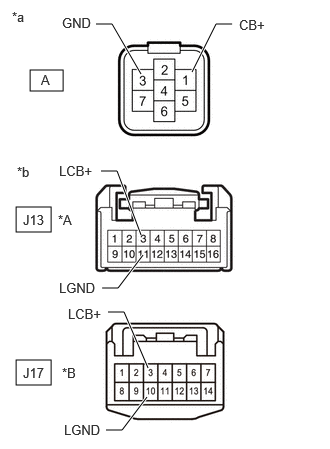
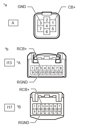
E453502C05
0.313,0.729 0.656,0.948 0.344,0.219 0.167,2.156 0.531,2.417 0.365,0.26 0.167,3.75 0.531,4.01 0.365,0.26 2,0.75 2.25,0.25 2.25,0.25 2.417,0.25 true 1.052,1.781 1.219,1.781 1.219,1.781 1.469,2.448 true 1.063,3 1.229,3 1.229,3 1.49,2.656 true 1.125,3.25 1.292,3.25 1.292,3.25 1.542,3.833 true 1.104,4.479 1.271,4.479 1.271,4.479 1.531,4.135 true 1.469,0.771 1.167,0.25 1.167,0.25 1,0.25 true 0.125,0.094 0.438,0.292 0.313,0.198 10 false *a 0.177,1.708 0.49,1.906 0.313,0.198 10 false *b 0.427,0.75 0.74,0.948 0.313,0.198 10 false A 0.24,2.208 0.552,2.406 0.313,0.198 10 false J13 0.604,2.208 0.917,2.406 0.313,0.198 10 false *A 0.646,3.802 0.958,4 0.313,0.198 10 false *B 2.49,0.177 2.948,0.375 0.458,0.198 10 false CB+ 0.646,0.156 1.104,0.354 0.458,0.198 10 false GND 0.615,1.698 1.073,1.896 0.458,0.198 10 false LCB+ 0.615,2.917 1.073,3.115 0.458,0.198 10 false LGND 0.708,3.188 1.167,3.385 0.458,0.198 10 false LCB+ 0.667,4.396 1.125,4.594 0.458,0.198 10 false LGND 0.24,3.802 0.552,4 0.313,0.198 10 false J17
*A for SFTM Made with Blind Spot Monitor System, for GTMC Made
*B for SFTM Made without Blind Spot Monitor System
*a Front view of wire harness connector
(to Side Television Camera Assembly LH)
*b Front view of wire harness connector
(to Outer Rear View Mirror Assembly LH)


Disconnect the outer rear view mirror assembly LH connector.


b.

Disconnect the side television camera assembly LH connector.


c.

Measure the resistance according to the value(s) in the table below.

Standard Resistance:
for SFTM Made with Blind Spot Monitor System, for GTMC Made:
Tester Connection Condition Specified Condition
A-1 (CB+) - J13-3 (LCB+) Always Below 1 Ω
A-3 (GND) - J13-11 (LGND) Always Below 1 Ω

for SFTM Made without Blind Spot Monitor System:
Tester Connection Condition Specified Condition
A-1 (CB+) - J17-3 (LCB+) Always Below 1 Ω
A-3 (GND) - J17-10 (LGND) Always Below 1 Ω


Result:
Proceed to
OK
NG


OK

10.CHECK SIDE TELEVISION CAMERA ASSEMBLY LH

NG

10.CHECK SIDE TELEVISION CAMERA ASSEMBLY LH
a.

Replace the side television camera assembly LH with a new or normally functioning one.

Click hereAudio / Visual / Telematics>PARK ASSIST / MONITORING>TELEVISION CAMERA (for Side)>REMOVAL


Result:
Proceed to
NEXT


NEXT

11.CLEAR DTC
11.CLEAR DTC
a.

Clear the DTCs.

Chassis > Circumference Monitoring Camera Control Module > Clear DTCs
50002 470
Result:
Proceed to
NEXT


NEXT

12.CHECK FOR DTC
12.CHECK FOR DTC
a.

Check for DTCs.

Chassis > Circumference Monitoring Camera Control Module > Trouble Codes
50001 470
Result:
Result Proceed to
C168811 or C168812 are not output A
C168811 or C168812 is output B


A

END (SIDE TELEVISION CAMERA ASSEMBLY LH WASS DEFECTIVE)

B

13.INSPECT OUTER REAR VIEW MIRROR ASSEMBLY RH
a.
E453502C06
0.313,0.729 0.656,0.948 0.344,0.219 0.167,2.156 0.531,2.417 0.365,0.26 0.167,3.802 0.531,4.063 0.365,0.26 2,0.75 2.25,0.25 2.25,0.25 2.417,0.25 true 1.052,1.781 1.219,1.781 1.219,1.781 1.469,2.448 true 1.063,3 1.229,3 1.229,3 1.49,2.656 true 1.125,3.25 1.292,3.25 1.292,3.25 1.542,3.833 true 1.104,4.479 1.271,4.479 1.271,4.479 1.531,4.135 true 1.469,0.771 1.167,0.25 1.167,0.25 1,0.25 true 0.125,0.094 0.438,0.292 0.313,0.198 10 false *a 0.177,1.708 0.49,1.906 0.313,0.198 10 false *b 0.427,0.75 0.74,0.948 0.313,0.198 10 false A 0.24,2.208 0.552,2.406 0.313,0.198 10 false I13 0.604,2.208 0.917,2.406 0.313,0.198 10 false *A 0.615,3.823 0.927,4.021 0.313,0.198 10 false *B 2.49,0.177 2.948,0.375 0.458,0.198 10 false CB+ 0.646,0.156 1.104,0.354 0.458,0.198 10 false GND 0.615,1.698 1.073,1.896 0.458,0.198 10 false RCB+ 0.615,2.917 1.073,3.115 0.458,0.198 10 false RGND 0.708,3.188 1.167,3.385 0.458,0.198 10 false RCB+ 0.667,4.396 1.125,4.594 0.458,0.198 10 false RGND 0.26,3.833 0.573,4.031 0.313,0.198 10 false I17
*A for SFTM Made with Blind Spot Monitor System, for GTMC Made
*B for SFTM Made without Blind Spot Monitor System
*a Front view of wire harness connector
(to Side Television Camera Assembly RH)
*b Front view of wire harness connector
(to Outer Rear View Mirror Assembly RH)


Disconnect the side television camera assembly RH connector.


b.

Disconnect the outer rear view mirror assembly RH connector.


c.

Measure the resistance according to the value(s) in the table below.

Standard Resistance:
for SFTM Made with Blind Spot Monitor System, for GTMC Made:
Tester Connection Condition Specified Condition
A-1 (CB+) - I13-3 (RCB+) Always Below 1 Ω
A-3 (GND) - I13-11 (RGND) Always Below 1 Ω

for SFTM Made without Blind Spot Monitor System:
Tester Connection Condition Specified Condition
A-1 (CB+) - I17-3 (RCB+) Always Below 1 Ω
A-3 (GND) - I17-10 (RGND) Always Below 1 Ω


Result:
Proceed to
OK
NG


OK

14.CHECK SIDE TELEVISION CAMERA ASSEMBLY RH

NG

14.CHECK SIDE TELEVISION CAMERA ASSEMBLY RH
a.

Replace the side television camera assembly RH with a new or normally functioning one.

Click hereAudio / Visual / Telematics>PARK ASSIST / MONITORING>TELEVISION CAMERA (for Side)>REMOVAL


Result:
Proceed to
NEXT


NEXT

15.CLEAR DTC
15.CLEAR DTC
a.

Clear the DTCs.

Chassis > Circumference Monitoring Camera Control Module > Clear DTCs
50002 470
Result:
Proceed to
NEXT


NEXT

16.CHECK FOR DTC
16.CHECK FOR DTC
a.

Check for DTCs.

Chassis > Circumference Monitoring Camera Control Module > Trouble Codes
50001 470
Result:
Result Proceed to
C168811 or C168812 are not output A
C168811/12 is output B


A

END (SIDE TELEVISION CAMERA ASSEMBLY RH WAS DEFECTIVE)

B