K121F CVT SHIFT LEVER POSITION SENSOR INSTALLATION
PROCEDURE

 84540
1.INSTALL SHIFT LEVER POSITION SENSOR
84540
1.INSTALL SHIFT LEVER POSITION SENSOR
Temporarily install the shift lever position sensor to the transaxle case sub-assembly with the 2 bolts.
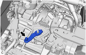
Temporarily install the transmission control shaft lever to the manual valve lever shaft.
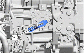
| *a | N |
Turn the transmission control shaft lever clockwise until it stops, then turn it counterclockwise 2 notches.
- NOTICE:
-
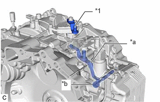 1.615,0.552 1.823,0.25 1.823,0.25 1.99,0.25 true 1.958,1.344 2.25,0.938 2.25,0.938 2.729,0.938 true 1.531,1.813 1.99,1.813 true 2.042,0.146 2.323,0.385 0.281,0.24 10 false *1 2.792,0.813 3.073,1.052 0.281,0.24 10 false *a 1.323,1.708 1.521,1.938 0.198,0.229 10 true *b
*1 Transmission Control Shaft Lever *a Manual Valve Link Lever Sub-assembly *b Manual Valve
-
If the transmission control shaft lever is turned counterclockwise more than necessary, manual valve link lever sub-assembly may separate from the manual valve.
Remove the transmission control shaft lever from the manual valve lever shaft.
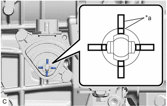
| *a | Protrusion |
Align the protrusions of the shift lever position sensor as shown in the illustration.
Hold the shift lever position sensor in that position and tighten the 2 bolts.
- Torque:
- 5.4 N*m (55 kgf*cm, 48 in.*lbf)
Install the transmission control shaft lever to the manual valve lever shaft with the washer and nut.
- Torque:
- 12.7 N*m (130 kgf*cm, 9 ft.*lbf)
- NOTICE:
-
Be careful of the direction of the transmission control shaft lever.
Connect the shift lever position sensor connector.
33820B
2.CONNECT TRANSMISSION CONTROL CABLE ASSEMBLY
- NOTICE:
-
Before connecting the transmission control cable assembly, check that the shift lever is in N.
| *a | N |
Turn the transmission control shaft lever clockwise until it stops, then turn it counterclockwise 2 notches.
- NOTICE:
-
1.615,0.552 1.823,0.25 1.823,0.25 1.99,0.25 true 1.958,1.344 2.25,0.938 2.25,0.938 2.729,0.938 true 1.531,1.813 1.99,1.813 true 2.042,0.146 2.323,0.385 0.281,0.24 10 false *1 2.792,0.813 3.073,1.052 0.281,0.24 10 false *a 1.323,1.708 1.521,1.938 0.198,0.229 10 true *b
*1 Transmission Control Shaft Lever *a Manual Valve Link Lever Sub-assembly *b Manual Valve
-
If the transmission control shaft lever is turned counterclockwise more than necessary, manual valve link lever sub-assembly may separate from the manual valve.
Connect the transmission control cable assembly to the No. 1 transmission control cable bracket with a new clip.

| *a | Correct |
| *b | Incorrect |
Connect the transmission control cable assembly to the transmission control shaft lever as shown in the illustration.
74404B
3.INSTALL BATTERY CLAMP SUB-ASSEMBLY
89661
4.INSTALL ECM
5.INSTALL BATTERY
6.INSPECT SHIFT LEVER POSITION SENSOR POSITION
7.ADJUST SHIFT LEVER POSITION SENSOR POSITION
8.INSPECT SHIFT LEVER POSITION
9.ADJUST SHIFT LEVER POSITION