K121F CVT TORQUE CONVERTER AND DRIVE PLATE INSPECTION
PROCEDURE

 1.INSPECT TORQUE CONVERTER ASSEMBLY

|
Difficult |

|
Smooth |
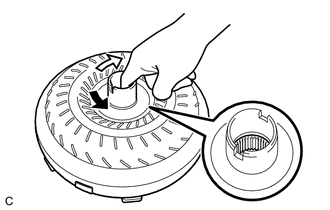
Inspect the one-way clutch. Press on the splines of the stator with a finger and rotate it. Check that it rotates smoothly when turned clockwise and rotates with difficulty when turned counterclockwise.
If necessary, clean the torque converter assembly and recheck the one-way clutch. Replace the torque converter assembly if the one-way clutch still fails the inspection.
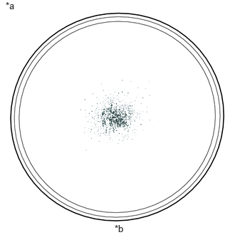
| *a | Sample showing maximum allowable amount of powder in fluid |
| *b | Full Scale |
Inspect the torque converter assembly.
If any of the following problems are present, replace the torque converter assembly.
A metallic sound is emitted from the torque converter assembly during the stall test or when the shift lever is moved to N.
The one-way clutch turns smoothly or difficulty in both directions.
The amount of powder in the fluid is more than the sample shown in the illustration (refer to the sample).
- HINT:
-
The sample shows approximately 0.025 liters (0.026 US qts, 0.022 Imp. qts) of fluid in a Petri dish, which has been taken from the removed torque converter assembly.
Replace the fluid in the torque converter assembly.
- HINT:
-
If the fluid is discolored or has a foul odor, stir the fluid in the torque converter assembly and drain it before replacing the fluid.
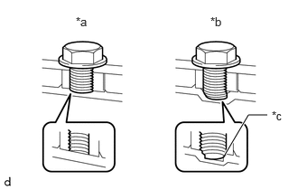
| *a | Correct |
| *b | Incorrect |
| *c | Bottom is damaged |
Prevent deformation of the torque converter assembly and damage to the oil pump gear.
- NOTICE:
-
Make sure that all of the bolts are the same length and that the specified bolts are used.
- HINT:
-
If there is any damage to the tip of a bolt for the torque converter assembly or to the bottom of a bolt hole, replace the bolt and torque converter assembly.
32101B
2.INSPECT DRIVE PLATE AND RING GEAR SUB-ASSEMBLY

|
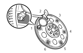
Measurement Point |
Check the drive plate and ring gear sub-assembly for damage.
Set up a dial indicator and measure the runout at the 6 areas on the drive plate and ring gear sub-assembly surface that contact the torque converter assembly.
- Maximum Runout:
0.30 mm (0.0118 in.)
- HINT:
- ·
If the runout is more than the maximum or the drive plate and ring gear sub-assembly is damaged, replace the drive plate and ring gear sub-assembly.
·If installing a new drive plate and ring gear sub-assembly, confirm that the spacers are oriented properly before tightening the bolts.