GF2A TRANSFER / 4WD / AWD TRANSFER ASSEMBLY INSTALLATION
PROCEDURE

 1.INSTALL WIRING HARNESS CLAMP BRACKET
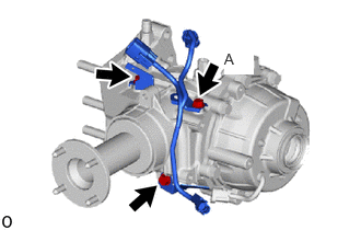
Install the 3 wiring harness clamp brackets and connect the clutch control solenoid wire with the 3 bolts.
- Torque:
- 19.6 N*m (200 kgf*cm, 14 ft.*lbf)
- HINT:
-
Tighten the ground of the clutch control solenoid wire together with bolt A.
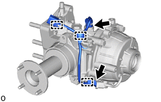
Connect the 3 clamps and 2 connectors and install the clutch control solenoid wire.
36100A
2.INSTALL TRANSFER AND TRANSAXLE SETTING STUD BOLT
36100
3.INSTALL TRANSFER ASSEMBLY
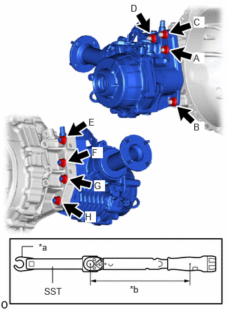
| *a | Union Nut Wrench |
| *b | Torque Wrench Fulcrum Length |
Clean the bolt holes.
Temporarily install the transfer assembly to the transaxle with the 8 nuts.
- NOTICE:
- ·
Push the transfer assembly by hand until it is in close contact with the mating surface of the transaxle assembly.
·If the entire mating surface does not come into close contact, tighten the nuts alternately in the order of nut A and nut B, and bring the mating surfaces into close contact little by little.
·Make sure the mating surfaces of nut A and nut B are in close contact. Then temporarily tighten the nuts in order as follows and bring the entire circumference of the mating surface in close contact.
- HINT:
-
Temporarily install order: Temporarily install nut (A) → Temporarily install nut (B) → Temporarily install nut (C) → Temporarily install nut (D) → Temporarily install nut (E) → Temporarily install nut (F) → Temporarily install nut (G) → Temporarily install nut (H)
Using SST and union nut wrench, tighten the 8 nuts.
- SST
- 09961-00950
- Torque:
- Specified tightening torque : 68.6 N*m (700 kgf*cm, 51 ft.*lbf)
- HINT:
- ·
Tightening order: Tighten nut (A) → Tighten nut (B) → Tighten nut (C) → Tighten nut (D) → Tighten nut (E) → Tighten nut (F) → Tighten nut (G) → Tighten nut (H)
·This torque value is effective when SST is straight to a torque wrench.
·Calculate the torque wrench reading when changing the fulcrum length of the torque wrench.
·When using a union nut wrench (fulcrum length of 30 mm (1.181 in.)) + SST (fulcrum length of 150 mm (5.906 in.)) + torque wrench (fulcrum length of 255 mm (10.039 in.)): 40.2 N*m (410 kgf*cm, 30 ft.*lbf)
12303
4.INSTALL REAR ENGINE MOUNTING BRACKET SUB-ASSEMBLY
12371A
5.INSTALL REAR ENGINE MOUNTING INSULATOR
37109
6.INSTALL NO. 1 PROPELLER SHAFT HEAT INSULATOR BRACKET SUB-ASSEMBLY
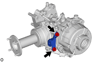
Install the No. 1 propeller shaft heat insulator bracket sub-assembly with the 2 bolts.
- Torque:
- 25 N*m (255 kgf*cm, 18 ft.*lbf)
37117
7.INSTALL PROPELLER SHAFT HEAT INSULATOR
8.INSTALL TRANSAXLE ASSEMBLY
9. DYNAMIC TORQUE VECTORING 4WD/AWD SYSTEM CALIBRATION
When the electro magnetic control coupling sub-assembly is replaced, Learning Value Initialization must be performed.