DRIVE SHAFT / PROPELLER SHAFT FRONT DRIVE SHAFT ASSEMBLY(for 2WD) INSTALLATION
PROCEDURE

 43420G
1.INSTALL FRONT DRIVE SHAFT HOLE SNAP RING LH
43420G
1.INSTALL FRONT DRIVE SHAFT HOLE SNAP RING LH
Install a new front drive shaft hole snap ring LH.
43420
2.INSTALL FRONT DRIVE SHAFT ASSEMBLY LH
Coat the spline of the inboard joint shaft assembly with MP grease.
for Gasoline model:
Coat the splines of the front drive inboard joint assembly with Toyota Genuine CVT fluid FE.
for HV model:
Coat the splines of the front drive inboard joint assembly with Toyota Genuine ATF WS.
Set the front drive shaft hole snap ring LH with the opening side facing down.
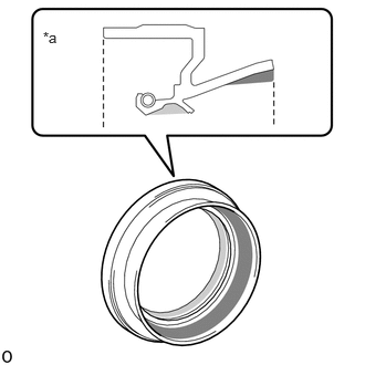
| *a | Cross Section of Front Drive Shaft Oil Seal LH |

|
MP Grease |

|
Toyota Genuine Oil Seal Side Lip Grease |
Coat the lip of the front drive shaft oil seal LH with MP grease and Toyota genuine oil seal side lip grease as shown in the illustration.
- HINT:
-
Apply a light coat of MP grease and Toyota genuine oil seal side lip grease to the entire circumference of the front drive shaft oil seal LH.
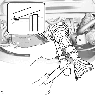
Align the splines and tap in the front drive shaft assembly with a brass bar and hammer.
- NOTICE:
- ·
Using MP grease, set the front drive shaft hole snap ring in the groove with the opening facing downwards and centered radially.
·Be careful not to damage the oil seal, front axle inboard joint boot and front drive shaft dust cover.
43410
3.INSTALL FRONT DRIVE SHAFT ASSEMBLY RH
for Gasoline model:
Coat the splines of the front drive inboard joint assembly with Toyota Genuine CVT fluid FE.
for HV model:
Coat the splines of the front drive inboard joint assembly with Toyota Genuine ATF WS.
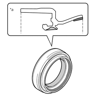
| *a | Cross Section of Front Drive Shaft Oil Seal RH |
|
|
MP Grease |
|
|
Toyota Genuine Oil Seal Side Lip Grease |
Coat the lip of the front drive shaft oil seal RH with MP grease and Toyota genuine oil seal side lip grease as shown in the illustration.
- HINT:
-
Apply a light coat of MP grease and Toyota genuine oil seal side lip grease to the entire circumference of the front drive shaft oil seal RH.
Align the inboard joint splines, and securely insert the front drive shaft assembly RH.
- NOTICE:
- ·
Do not damage the front drive shaft oil seal RH.
·Do not damage the front axle inboard joint boot.
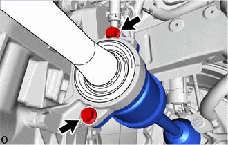
Install the front drive shaft assembly RH with the 2 bolts.
- Torque:
- 50.5 N*m (515 kgf*cm, 37 ft.*lbf)
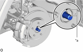
| *a | Matchmark |
Align the matchmarks and install the front drive shaft assembly RH to the front axle hub sub-assembly.
- NOTICE:
- ·
Do not push the front axle assembly further out of the vehicle than is necessary.
·Be careful not to damage the front axle outboard joint boot.
·Check for any foreign matter on the speed sensor rotor and insertion part.
·Do not damage the speed sensor rotor.
4.CONNECT STEERING KNUCKLE WITH AXLE HUB LH
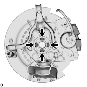

|
Toyota Body Grease W |
Apply MP grease to the entire contact surface between the front drive shaft assembly and axle hub bearing surface or only apply 0.1 to 0.3 g (0.00353 to 0.0105 oz.) of Toyota Body Grease W to the 4 areas on the axle hub bearing shown in the illustration.
Align the matchmarks and connect the steering knuckle with axle hub LH.
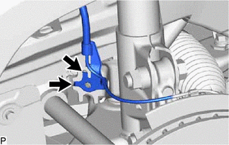
|
|
Hook |
Set the 2 front speed sensor LH hooks on the front shock absorber assembly LH.
- NOTICE:
-
Do not twist the front speed sensor when installing it.
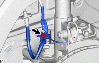
Install the front speed sensor and front flexible hose to the front shock absorber assembly with the bolt.
- Torque:
- 29 N*m (296 kgf*cm, 21 ft.*lbf)
- NOTICE:
-
Do not twist the front flexible hose when installing it.
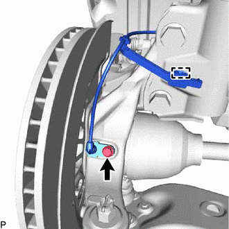
Install the front speed sensor to the steering knuckle with the bolt.
- Torque:
- 8.5 N*m (87 kgf*cm, 75 in.*lbf)
- NOTICE:
- ·
Prevent foreign matter from attaching to the front speed sensor tip.
·Firmly insert the front speed sensor body into the steering knuckle before tightening the bolt.
·After installing the front speed sensor to the steering knuckle, make sure that there is no clearance between the front speed sensor stay and steering knuckle. Also make sure that no foreign matter is stuck between the parts.
·Do not twist the front speed sensor when installing it.
Engage the clamp.
- NOTICE:
-
Do not twist the front speed sensor when installing it.
5.CONNECT STEERING KNUCKLE WITH AXLE HUB RH
- HINT:
-
Use the same procedure described for the LH side.
48069
6.CONNECT FRONT LOWER NO. 1 SUSPENSION ARM SUB-ASSEMBLY LH
48068
7.CONNECT FRONT LOWER NO. 1 SUSPENSION ARM SUB-ASSEMBLY RH
- HINT:
-
Use the same procedure described for the LH side.
48810
8.CONNECT FRONT STABILIZER LINK ASSEMBLY LH
48820B
9.CONNECT FRONT STABILIZER LINK ASSEMBLY RH
- HINT:
-
Use the same procedure described for the LH side.
10.CONNECT FRONT SPEED SENSOR LH
11.CONNECT FRONT SPEED SENSOR RH
- HINT:
-
Use the same procedure described for the LH side.
43502H
12.INSTALL FRONT AXLE SHAFT NUT LH
Install the front axle shaft nut LH.
Stake the front axle shaft nut LH.
43501H
13.INSTALL FRONT AXLE SHAFT NUT RH
- HINT:
-
Use the same procedure described for the LH side.
14.ADD TRANSAXLE OIL
for Hybrid Vehicle Transaxle: Click hereGeneral>MAINTENANCE>P710 HYBRID TRANSAXLE FLUID>REPLACEMENT202104,999999,_V1,_083136,_0400798,RM100000001WHMW,
15.INSPECT FOR OIL LEAK
53737D
16.INSTALL FRONT FENDER APRON SEAL LH
53736E
17.INSTALL FRONT FENDER APRON SEAL RH
51420
18.INSTALL NO. 2 ENGINE UNDER COVER ASSEMBLY
19.INSTALL FRONT WHEEL
20.CHECK SPEED SENSOR SIGNAL
21.INSPECT AND ADJUST FRONT WHEEL ALIGNMENT