HEATING / AIR CONDITIONING REFRIGERANT LINE(for Gasoline Model) INSTALLATION
PROCEDURE

 88718L
1.INSTALL PIPING CLAMP (for Suction Hose Sub-assembly Side)
88718L
1.INSTALL PIPING CLAMP (for Suction Hose Sub-assembly Side)
Remove the vinyl tape from the suction hose sub-assembly and suction tube sub-assembly B.
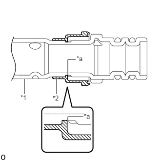
| *1 | Suction Hose Sub-assembly |
| *2 | Piping Clamp |
| *a | Groove |
Install a new piping clamp to the suction hose sub-assembly.
- NOTICE:
- ·
Securely engage the piping clamp to the groove of the suction hose sub-assembly.
·Do not open the piping clamp more than the diameter of the suction hose sub-assembly when installing it.
·Do not install the piping clamp with the large diameter section facing the wrong direction.
·Before installing, remove any foreign matter adhered to the fitting area.
Sufficiently apply compressor oil to 2 new O-rings and the fitting surfaces of the suction hose sub-assembly.
- Compressor Oil:
ND-OIL 8 or equivalent
Install the 2 O-rings to the suction hose sub-assembly.
- NOTICE:
-
Keep the O-rings and O-ring fitting surfaces free from dirt and foreign matter.
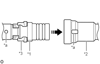
| *1 | Suction Hose Sub-assembly |
| *2 | Suction Tube Sub-assembly B |
| *3 | Piping Clamp |
| *a | Alignment Mark |

|
Install in this Direction |
Align the alignment marks and connect the suction hose sub-assembly and suction tube sub-assembly B.
- NOTICE:
- ·
Connect the parts by holding the pipe, not the piping clamp.
·Do not apply excessive force to the suction hose sub-assembly and suction tube sub-assembly B.
·Make sure not to cut the O-ring while installing it. (Cut O-rings cannot be installed)
·Before connecting, remove any foreign matter adhered to the fitting area.
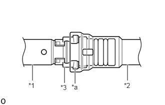
| *1 | Suction Hose Sub-assembly |
| *2 | Suction Tube Sub-assembly B |
| *3 | Piping Clamp |
| *a | Large Diameter Section of Piping Clamp |
Securely insert the piping clamp to the point where the large diameter section of the piping clamp is covered by the suction tube sub-assembly B.
- NOTICE:
- ·
Securely insert until the piping clamp claw enters the suction tube sub-assembly B.
 2.552,1.656 2.552,1.323 true 4.76,1.719 4.76,1.385 true 2.969,1.656 2.969,1.323 true 2.469,1.646 2.781,1.844 0.313,0.198 10 false *1 4.688,1.719 5,1.917 0.313,0.198 10 false *2 2.885,1.656 3.198,1.854 0.313,0.198 10 false *3 1.125,2.104 1.438,2.302 0.313,0.198 10 false *a 3.906,2.104 4.219,2.302 0.313,0.198 10 false *b
*1 Suction Hose Sub-assembly *2 Suction Tube Sub-assembly B *3 Piping Clamp - - *a OK *b NG
·When inserting, make sure that a click sound is heard.
·Check that the suction hose sub-assembly is securely connected by pulling it.
88718N
2.INSTALL PIPING CLAMP (for Air Conditioning Tube and Accessory Assembly Side)
3.CHARGE AIR CONDITIONING SYSTEM WITH REFRIGERANT
4.WARM UP ENGINE
5.INSPECT FOR REFRIGERANT LEAK