THEFT DETERRENT / KEYLESS ENTRY IMMOBILISER SYSTEM(w/o Smart Entry and Start System) Key Cannot be Registered
DESCRIPTION
A maximum of 5 key ID codes can be registered.
WIRING DIAGRAM
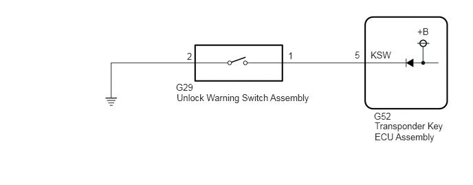
CAUTION / NOTICE / HINT
- NOTICE:
- ·
Before replacing the transponder key ECU assembly or door control transmitter assembly, refer to the Service Bulletin.
·Make sure that no DTCs are output. If any DTCs are output, proceed to the Diagnostic Trouble Code Chart.
·After completing repairs, confirm that the problem does not recur.
·After repair, confirm that no DTCs are output by performing "DTC Output Confirmation Operation".
PROCEDURE
Check that the system enters registration mode.
- OK:
System enters registration mode.
- Result:
Proceed to OK NG
OK
NG
In registration mode, insert the door control transmitter assembly into the ignition key cylinder and check the combination meter assembly (security indicator light).
- HINT:
-
If the new key ID code registration fails, code 2-1 will be output through the security light. Trying to re-register an already registered door control transmitter assembly will cause code 2-2 to be output when the door control transmitter assembly is inserted. If the number of registered key ID codes exceeds the maximum limit, code 2-3 will be output through the combination meter assembly (security indicator light). The output details are shown in the following illustration.
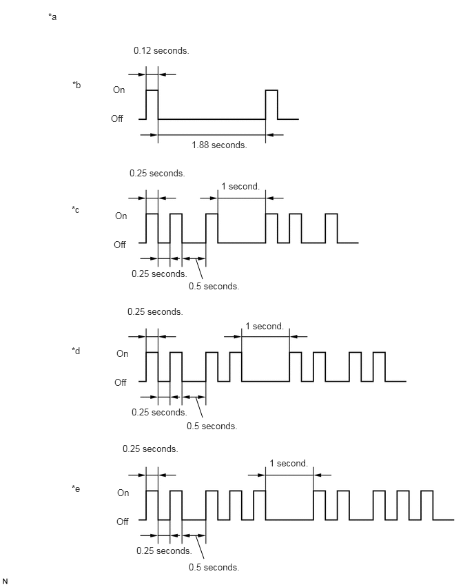
| *a | Combination Meter Assembly (Security Indicator Light) | *b | Normal (Immobiliser system is operating normally) |
| *c | Code 2-1 | *d | Code 2-2 |
| *e | Code 2-3 | - | - |
- Result:
Result Proceed to Code 2-1 or Code 2-3 is output A Code 2-2 is output B
A
B
Connect the GTS to the DLC3.
Turn the ignition switch to ON.
Turn the GTS on.
Enter the following menus: Body Electrical / Immobiliser / Data List.
Read the Data List according to the display on the GTS.
- Body Electrical > Immobiliser > Data List
-
Tester Display Measurement Item Range Normal Condition Diagnostic Note Transponder M-code Number of registered master keys Min. : 0, Max. : 15 Number of registered master keys displayed -
- Body Electrical > Immobiliser > Data List
-
Tester Display Transponder M-code - 50003 260 19
- Result:
Result Proceed to 5 is displayed for "Transponder M-code" A Values are other than above B
A
B
Refer to the table below to determine if additional door control transmitter assemblies can be registered.
| Number of Door Control Transmitter Assemblies Registered | Proceed to |
|---|---|
| 0 | New key ID code registration |
| 1 to 4 | Additional key ID code registration |
Check if an additional door control transmitter assembly can be registered.
- OK:
Additional door control transmitter assembly can be registered.
- Result:
Proceed to OK NG
OK
NG
Remove the unlock warning switch assembly.
Inspect the unlock warning switch assembly.
- Result:
Proceed to OK NG
OK
NG
Disconnect the G52 transponder key ECU assembly connector.
Measure the resistance according to the value(s) in the table below.
- Standard Resistance:
Tester Connection Condition Specified Condition G29-1 - G52-5 (KSW) Always Below 1 Ω G29-2 - Body ground Always Below 1 Ω G29-1 or G52-5 (KSW) - Other terminals and body ground Always 10 kΩ or higher
- Result:
Proceed to OK NG
OK
NG