WINDOW / GLASS POWER WINDOW CONTROL SYSTEM Front Passenger Side Power Window Auto Up / Down Function does not Operate with Front Passenger Side Power Window Switch
DESCRIPTION
If the manual up and down function operates normally but the auto up and down function does not, then fail-safe mode may be functioning.
If power window initialization has not been performed, the auto up and down function will not operate.
WIRING DIAGRAM
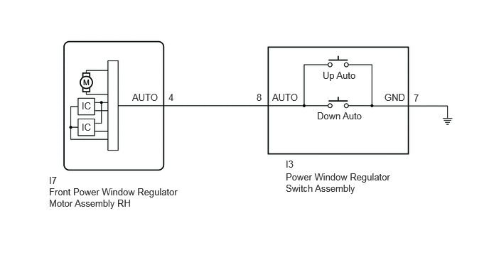
CAUTION / NOTICE / HINT
- NOTICE:
- ·
If the front power window regulator motor assembly has been replaced with a new one, initialize the power window control system.
·Check that the "P Window Auto Up" and "P Window Auto Down" power window control system customize settings are "ON" before proceeding with work.
·After the catch protection function operates, the auto operation is not performed the first time auto up is performed. All auto up operations performed after the first operate normally.
- HINT:
-
If the pulse sensor built into the front power window regulator motor assembly is malfunctioning, the power window control system enters fail-safe mode. The remote up and down and auto up and down functions cannot be operated during fail-safe mode. However, the power window can be closed by holding the power window regulator switch assembly at the auto up position, and opened manually by pushing down the power window regulator switch assembly.
PROCEDURE
Using the GTS, read the data for the condition when the power window regulator switch assembly was operated.
- Body Electrical > P-Door Motor > Data List
-
Tester Display Measurement Item Range Normal Condition Diagnostic Note P Door P/W Auto SW Front passenger door power window auto switch signal OFF or ON OFF: Front passenger door power window auto switch not being operated
ON: Front passenger door power window auto switch being operated-
- Body Electrical > P-Door Motor > Data List
-
Tester Display P Door P/W Auto SW - 50003 144 1
- OK:
On the GTS screen, ON or OFF is displayed accordingly.
- Result:
Proceed to OK NG
OK
NG
Initialize the front power window regulator motor assembly RH.
- OK:
Power window system operates normally.
- Result:
Proceed to OK NG
OK
NG
Remove the power window regulator switch assembly.
Inspect the power window regulator switch assembly.
- Result:
Proceed to OK NG
OK
NG
Disconnect the I3 power window regulator switch assembly connector.
Disconnect the I7 front power window regulator motor assembly RH connector.
Measure the resistance according to the value(s) in the table below.
- Standard Resistance:
Tester Connection Condition Specified Condition I3-8 (AUTO) - I7-4 (AUTO) Always Below 1 Ω I3-8 (AUTO) or I7-4 (AUTO) - Body ground Always 10 kΩ or higher
- Result:
Proceed to OK NG
OK
NG