RM3660EC _56 Audio / Visual / Telematics _080754 PARK ASSIST / MONITORING _0596562 REAR VIEW MONITOR SYSTEM J

PARK ASSIST / MONITORING  REAR VIEW MONITOR SYSTEM  Image from Camera for Rear View Monitor is Abnormal  


DESCRIPTION

The video signal of the rear television camera assembly is transmitted to the radio and display receiver assembly.

WIRING DIAGRAM
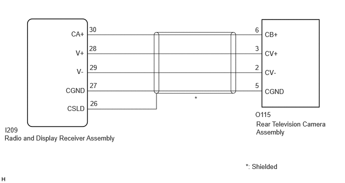
E432751E26
5.302,2.302 6.365,2.615 1.063,0.313 10 false O115 5.323,2.5 6.792,2.969 1.469,0.469 10 false Rear Television Camera Assembly 5.5,0.635 5.927,0.865 0.427,0.229 10 false CB+ 5.5,1.031 5.938,1.333 0.438,0.302 10 false CV+ 5.5,1.427 5.865,1.708 0.365,0.281 10 false CV- 5.5,1.823 5.99,2.01 0.49,0.188 10 false CGND 1.479,0.625 1.938,0.885 0.458,0.26 10 false CA+ 1.573,1.021 1.896,1.26 0.323,0.24 10 false V+ 1.594,1.406 1.917,1.698 0.323,0.292 10 false V- 1.365,1.802 1.938,2.125 0.573,0.323 10 false CGND 0.104,2.625 0.5,2.813 0.396,0.188 10 false I209 5.302,0.542 5.531,0.844 0.229,0.302 10 false 6 5.302,0.927 5.542,1.25 0.24,0.323 10 false 3 5.302,1.323 5.49,1.615 0.188,0.292 10 false 2 5.302,1.698 5.458,1.917 0.156,0.219 10 false 5 4.042,1.979 4.188,2.135 0.146,0.156 10 false * 5.104,3.385 5.917,3.583 0.813,0.198 10 false *: Shielded 1.854,0.531 2.344,0.875 0.49,0.344 10 false 30 1.854,0.927 2.24,1.156 0.385,0.229 10 false 28 1.865,1.323 2.24,1.583 0.375,0.26 10 false 29 1.865,1.698 2.292,1.938 0.427,0.24 10 false 27 0.094,2.792 2.583,3.021 2.49,0.229 10 false Radio and Display Receiver Assembly 1.875,2.073 2.302,2.313 0.427,0.24 10 false 26 1.396,2.177 1.969,2.5 0.573,0.323 10 false CSLD

PROCEDURE

1.CHECK HARNESS AND CONNECTOR (RADIO AND DISPLAY RECEIVER ASSEMBLY - REAR TELEVISION CAMERA ASSEMBLY)
a.

Disconnect the I209 radio and display receiver assembly connector.

b.

Disconnect the O115 rear television camera assembly connector.

c.

Measure the resistance according to the value(s) in the table below.

Standard Resistance:
Tester Connection Condition Specified Condition
I209-30 (CA+) - O115-6 (CB+) Always Below 1 Ω
I209-28 (V+) - O115-3 (CV+) Always Below 1 Ω
I209-29 (V-) - O115-2 (CV-) Always Below 1 Ω
I209-27 (CGND) - O115-5 (CGND) Always Below 1 Ω
I209-26 (CSLD) - Body ground Always Below 1 Ω
I209-30 (CA+) or O115-6 (CB+) - Body ground Always 10 kΩ or higher
I209-28 (V+) or O115-3 (CV+) - Body ground Always 10 kΩ or higher
I209-29 (V-) or O115-2 (CV-) - Body ground Always 10 kΩ or higher
I209-27 (CGND) or O115-5 (CGND) - Body ground Always 10 kΩ or higher


Result:
Proceed to
OK
NG


OK

2.INSPECT RADIO AND DISPLAY RECEIVER ASSEMBLY

NG

REPAIR OR REPLACE HARNESS OR CONNECTOR

2.INSPECT RADIO AND DISPLAY RECEIVER ASSEMBLY
a.

Reconnect the I209 radio and display receiver assembly connector.


b.
E504654C09
1.458,0.156 1.875,0.406 0.417,0.25 1.354,1.292 2.188,1.865 2.188,1.865 2.354,1.865 false 0.99,1.292 0.99,1.875 0.99,1.875 0.823,1.875 false 0.813,1.208 0.5,1.01 0.5,1.01 0.344,1.01 false 1.521,0.198 1.833,0.396 0.313,0.198 10 false I209 0.125,0.063 0.438,0.26 0.313,0.198 10 false *a 2.406,1.792 2.99,2.031 0.583,0.24 10 false CGND 0.625,1.781 0.979,2 0.354,0.219 10 false V- 0.063,0.938 0.417,1.156 0.354,0.219 10 false CA+
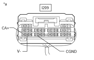
*a Component with harness connected
(Radio and Display Receiver Assembly)


Measure the resistance according to the value(s) in the table below.

Standard Resistance:
Tester Connection Condition Specified Condition
I209-29 (V-) - Body ground Always Below 1 Ω
I209-27 (CGND) - Body ground Always Below 1 Ω


c.

Measure the voltage according to the value(s) in the table below.

Standard Voltage:
Tester Connection Condition Specified Condition
I209-30 (CA+) - I209-27 (CGND) Ignition switch ACC 5.5 to 7.05 V


Result:
Proceed to
OK
NG


OK

3.INSPECT REAR TELEVISION CAMERA ASSEMBLY

NG

3.INSPECT REAR TELEVISION CAMERA ASSEMBLY
a.

Reconnect the O115 rear television camera assembly connector.


b.
E504654C10
1.417,0.125 1.906,0.406 0.49,0.281 0.969,1.208 0.802,1.104 0.802,1.104 0.302,1.104 true 0.583,1.833 0.74,1.833 0.74,1.833 1.083,1.281 true 1.51,0.177 1.948,0.458 0.438,0.281 10 false I209 0.177,0.135 0.49,0.333 0.313,0.198 10 false *a 0.375,1.76 0.833,1.958 0.458,0.198 10 false V+ 0.083,1.052 0.396,1.25 0.313,0.198 10 false V-
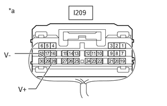
*a Component with harness connected
(Radio and Display Receiver Assembly)


E265840C01
0.823,2.073 1,2.073 1,2.073 1.125,1.583 false 1.479,2.063 1.344,2.063 1.344,2.063 1.229,1.479 false 0.781,4.167 0.958,4.167 0.958,4.167 1.156,3.594 false 1.521,4.125 1.385,4.125 1.385,4.125 1.271,3.542 false 0.229,0.229 0.542,0.427 0.313,0.198 10 *a 0.396,1.052 0.76,1.313 0.365,0.26 10 GND 0.396,3.208 0.76,3.469 0.365,0.26 10 GND 0.26,2.271 0.625,2.531 0.365,0.26 10 *b 0.646,4.073 1.01,4.333 0.365,0.26 10 *c 0.656,1.979 1.021,2.24 0.365,0.26 10 *c 1.51,1.969 1.875,2.229 0.365,0.26 10 *d 1.542,4.052 1.906,4.313 0.365,0.26 10 *d
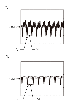
*a Waveform 1 (camera lens is not covered, displaying an image)
*b Waveform 2 (camera lens is covered, blacking out the screen)
*c Synchronization Signal
*d Video Waveform


Using an oscilloscope, check the waveform of the rear television camera assembly.

HINT:

A waterproof connector is used for the rear television camera assembly. Therefore, inspect the waveform at the radio and display receiver assembly with the connector connected.


OK:

Waveform is similar to that shown in the illustration.


Item Content
Measurement terminal I209-28 (V+) - I209-29 (V-)
Measurement setting 200 mV/DIV., 50 μs./DIV.
Condition Ignition switch ON, reverse (R) selected

HINT:
·

The video waveform changes according to the image sent by the rear television camera assembly.

·

The video waveform is constantly output when the ignition switch is turned to ACC.

·

Make sure that the rear camera is enabled in general settings.


Result:
Proceed to
OK
NG


OK

NG