LIGHTING (EXT) SIDE TURN SIGNAL LIGHT ASSEMBLY REMOVAL
CAUTION / NOTICE / HINT
The necessary procedures (adjustment, calibration, initialization, or registration) that must be performed after parts are removed and installed, or replaced during side turn signal light assembly removal/installation are shown below.
| Replaced Part or Performed Procedure | Necessary Procedure | Effect/Inoperative Function when Necessary Procedure not Performed | Link |
|---|---|---|---|
|
*: Even when not replacing the part, it is necessary to perform the specified necessary procedures after installation. |
|||
·
Side television camera assembly LH* ·
Side television camera assembly RH* ·
Outer rear view mirror assembly LH* ·
Outer rear view mirror assembly RH* |
Side television camera view adjustment | Panoramic View Monitor System | ( 202307,999999,_56,_080754,_0612151,RM100000002CL9H,) 202307,999999,_56,_080754,_0612151,RM100000002CL9H,)
|
Replacement or removal and installation of 2 or more parts:
·
Front television camera assembly, radiator grille sub-assembly or front bumper assembly ·
Side television camera assembly LH or outer rear view mirror assembly LH ·
Side television camera assembly RH or outer rear view mirror assembly RH ·
Rear television camera assembly |
Television camera view adjustment | Panoramic View Monitor System | (202307,999999,_56,_080754,_0612151,RM100000002CL9H,)
|
- HINT:
- ·
Use the same procedure for the RH side and LH side.
·The following procedure is for the LH side.
PROCEDURE

 87961
1.REMOVE OUTER MIRROR
87961
1.REMOVE OUTER MIRROR
2.REMOVE OUTER MIRROR COVER WITH OUTER MIRROR HOLE COVER (for GTMC Made)
87945
3.REMOVE OUTER MIRROR COVER (for GTMC Made)
87945
4.REMOVE OUTER MIRROR COVER (for TFTM Made)
5.REMOVE NO. 2 OUTER MIRROR COVER (for TFTM Made without Panoramic View Monitor System)
6.REMOVE OUTER MIRROR HOLE COVER WITH TELEVISION CAMERA (for TFTM Made with Panoramic View Monitor System)
81740
7.REMOVE SIDE TURN SIGNAL LIGHT ASSEMBLY
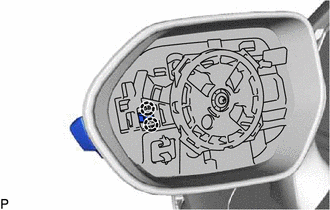
Disengage the 2 claws.
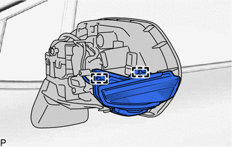
Disengage the 2 guides to separate the side turn signal light assembly.
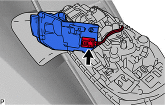
Disconnect the connector to remove the side turn signal light assembly.