METER / GAUGE / DISPLAY METER / GAUGE SYSTEM(for 12.3 Inch Display) Fuel Receiver Gauge Malfunction
DESCRIPTION
FUEL RECEIVER GAUGE DESCRIPTION
The combination meter assembly receives the fuel level signal via direct line from the fuel sender gauge assembly and the fuel consumption signal from the ECM via CAN communication, then calculates the fuel level in the fuel tank and displays the calculated value on the fuel receiver gauge.
FUEL RECEIVER GAUGE CONTROL
During normal driving:
During driving, the value of the fuel receiver gauge is updated based on the reduction in the fuel level. The reduction is calculated by deducting the value calculated based on the fuel consumption signal sent by the ECM from the value calculated based on the signal sent by the fuel sender gauge assembly.
During refueling:
As the fuel level in the fuel tank increases during refilling, the output value of the fuel sender gauge assembly changes. When the combination meter assembly detects a change in the output value of the fuel sender gauge assembly of a certain value or more, it determines that fuel is being added and calculates the added amount. This control is called refueling judgment and the fuel receiver gauge display is updated in accordance with the fuel level calculated based on the refueling judgment.
PRECAUTION FOR REFUELING
CAUTION / NOTICE / HINT
- NOTICE:
- ·
When replacing the combination meter assembly, always replace it with a new one. If a combination meter assembly which was installed to another vehicle is used, the information stored in it will not match the information from the vehicle and a DTC may be stored.
·When replacing the combination meter assembly, update the ECU security key.
·Before preforming this procedure, check for Meter / Gauge System DTC B150013 which is stored if an open or short in the circuit is detected. If DTC B150013 is output, perform troubleshooting and repairs as necessary.
·After the ignition switch is turned off, there may be a waiting time before disconnecting the negative (-) auxiliary battery terminal.
PROCEDURE
Choose the model to be inspected.
- Result:
Result Proceed to for HV Model A for Gasoline Model B
A
B
Check if CAN communication DTCs are output.
- Result:
Result Proceed to DTCs are not output A DTCs are output B
A
B
Check if electronically controlled brake system DTCs are output.
- Chassis > Brake/EPB > Trouble Codes
- 50001 435
- Chassis > Brake Booster > Trouble Codes
- 50001 466
- Result:
Result Proceed to DTCs are not output A DTCs are output B
A
B
Check the problem symptoms.
- Result:
Result Proceed to Malfunction occurs when adding fuel (Even when refueled, display value does not increase) A Malfunction occurs when adding fuel (When refueled, display value increase is slow) B Malfunction occurs during normal driving (The reading does not change, decreases quickly or decreases when the vehicle is not being driven, etc.)
(The problem symptom recurs)C Malfunction occurs during normal driving (The reading does not change, decreases quickly or decreases when the vehicle is not being driven, etc.)
(The problem symptom does not recur)D
A
B
C
D
Perform a manual update of the fuel receiver gauge.
Check that the display value of the fuel receiver gauge has changed.
- Result:
Result Proceed to Display value of the fuel receiver gauge has changed A Display value of the fuel receiver gauge has not changed B
A
- HINT:
-
It is suspected that the indicated value of the fuel receiver gauge did not automatically update due to the following reasons:
- ·
The amount of added fuel was less than the refueling judgement amount.
·Refueling was performed in a range for which detection is not possible (indicated value of fuel receiver gauge was near E or F)
B
Perform the Active Test according to the display on the GTS.
- Body Electrical > Combination Meter > Active Test
-
Tester Display Measurement Item Control Range Diagnostic Note Fuel Gauge Operation (Sender E) Fuel receiver gauge
(Fuel sender gauge lower limit)ON See [Display 1] Fuel Gauge Operation (Empty) Fuel receiver gauge
(Fuel receiver gauge indicates E)ON See [Display 1] Fuel Gauge Operation (Warning) Fuel receiver gauge
(Position at which fuel level warning light turns on/off)ON See [Display 1] Fuel Gauge Operation (1/4) Fuel receiver gauge
(Fuel receiver gauge indicates 1/4)ON See [Display 1] Fuel Gauge Operation (1/2) Fuel receiver gauge
(Fuel receiver gauge indicates 1/2)ON See [Display 1] Fuel Gauge Operation (3/4) Fuel receiver gauge
(Fuel receiver gauge indicates 3/4)ON See [Display 1] Fuel Gauge Operation (Full) Fuel receiver gauge
(Fuel receiver gauge indicates F)ON See [Display 1] Fuel Gauge Operation (Sender F) Fuel receiver gauge
(Fuel sender gauge upper limit)ON See [Display 1]
- HINT:
-
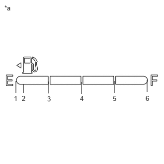 1.021,1.958 1.021,1.708 false 1.708,1.969 1.708,1.719 false 2.396,1.948 2.396,1.698 false 3.083,1.927 3.083,1.677 false 0.333,1.948 0.333,1.698 false 0.49,1.948 0.49,1.771 false 0.094,0.083 0.406,0.281 0.313,0.198 10 false *a 0.292,1.979 0.604,2.177 0.313,0.198 10 false 1 0.99,1.99 1.302,2.188 0.313,0.198 10 false 3 1.677,1.979 1.99,2.177 0.313,0.198 10 false 4 2.365,1.979 2.677,2.177 0.313,0.198 10 false 5 3.052,1.979 3.365,2.177 0.313,0.198 10 false 6 0.458,1.979 0.771,2.177 0.313,0.198 10 false 2
*a Fuel Receiver Gauge
- [Display 1]: Fuel Gauge Operation
Refer to the following table for the specified fuel receiver gauge position for each selected value:
Tester Display Fuel Receiver Gauge Indication Fuel Gauge Operation
(Sender E)Approximately 1 is indicated Fuel Gauge Operation
(Empty)Approximately 1 is indicated Fuel Gauge Operation
(Warning)Approximately 2 is indicated Fuel Gauge Operation
(1/4)Approximately 3 is indicated Fuel Gauge Operation
(1/2)Approximately 4 is indicated Fuel Gauge Operation
(3/4)Approximately 5 is indicated Fuel Gauge Operation
(Full)Approximately 6 is indicated Fuel Gauge Operation
(Sender F)Approximately 6 is indicated
- Body Electrical > Combination Meter > Active Test
-
Tester Display Fuel Gauge Operation (Sender E) - 50004 409 221
- Body Electrical > Combination Meter > Active Test
-
Tester Display Fuel Gauge Operation (Empty) - 50004 409 222
- Body Electrical > Combination Meter > Active Test
-
Tester Display Fuel Gauge Operation (Warning) - 50004 409 223
- Body Electrical > Combination Meter > Active Test
-
Tester Display Fuel Gauge Operation (1/4) - 50004 409 224
- Body Electrical > Combination Meter > Active Test
-
Tester Display Fuel Gauge Operation (1/2) - 50004 409 225
- Body Electrical > Combination Meter > Active Test
-
Tester Display Fuel Gauge Operation (3/4) - 50004 409 226
- Body Electrical > Combination Meter > Active Test
-
Tester Display Fuel Gauge Operation (Full) - 50004 409 227
- Body Electrical > Combination Meter > Active Test
-
Tester Display Fuel Gauge Operation (Sender F) - 50004 409 228
- Result:
Result Proceed to Active Test can be performed correctly A Active Test cannot be performed correctly B
A
B
- NOTICE:
-
As it is necessary to add more than a certain amount of fuel to the fuel tank, if the fuel level is near full (fuel receiver gauge indicator near F), perform the following procedure then proceed to step (a). If the fuel tank is not near full, proceed to step (a) without performing the following procedure.
- 1.
Turn the ignition switch off.
2.Remove 15 liters (15.9 US qts, 13.2 Imp. qts) or more of fuel from the fuel tank.
3.Turn the ignition switch to ON.
4.Wait 6 minutes or more.
5.Confirm that the fuel receiver gauge indicates a value in accordance with the removed amount of fuel.
Record the fuel receiver gauge reading.
Turn the ignition switch off.
Disconnect the cable from the negative (-) auxiliary battery terminal.
- HINT:
-
This resets the current fuel level information stored by the combination meter assembly.
Wait 2 minutes or more.
Connect the cable to the negative (-) auxiliary battery terminal.
Wait 15 seconds or more.
- HINT:
-
If the cable is disconnected from the negative (-) auxiliary battery terminal, the pressure inside the fuel tank will change. After the cable is reconnected to the negative (-) auxiliary battery terminal, it takes approximately 15 seconds for the pressure inside the fuel tank to be restored. During this time, the indicated value of the fuel receiver gauge may change.
Turn the ignition switch to ON.
Drive the vehicle at 2 km/h (1 mph) or more, and then stop the vehicle on a flat surface.
Turn the ignition switch off.
Wait 30 seconds or more.
Add the following amount of fuel or more.
2.0 liters (2.1 US qts, 1.8 Imp. qts)
Turn the ignition switch to ON.
Check that the fuel receiver gauge reading increases in proportion to the amount of fuel added.
- NOTICE:
-
After turning the ignition switch to ON, it may take approximately 30 seconds until the fuel receiver gauge indicates the determined value.
- Result:
Result Proceed to Fuel receiver gauge reading increases in proportion to the amount of fuel added A Fuel receiver gauge reading does not change even when fuel is added B
A
B
Check if SFI system DTCs are output.
- Powertrain > Engine > Trouble Codes
- 50001 372
- Result:
Result Proceed to DTCs are not output A DTCs are output B
A
B
PA10 HYBRID CONTROL SYSTEM (for LITHIUM-ION BATTERY): Click hereEngine / Hybrid System>HYBRID / BATTERY CONTROL>PA10 HYBRID CONTROL SYSTEM (for LITHIUM-ION BATTERY)>DIAGNOSTIC TROUBLE CODE CHART202304,999999,_51,_080773,_0600291,RM100000002BBUN,
PB10 HYBRID CONTROL SYSTEM (for LITHIUM-ION BATTERY): Click hereEngine / Hybrid System>HYBRID / BATTERY CONTROL>PB10 HYBRID CONTROL SYSTEM (for LITHIUM-ION BATTERY)>DIAGNOSTIC TROUBLE CODE CHART202307,999999,_51,_080773,_0615951,RM100000002CVAK,
Perform the Active Test according to the display on the GTS.
- Body Electrical > Combination Meter > Active Test
-
Tester Display Measurement Item Control Range Diagnostic Note Fuel Gauge Operation (Sender E) Fuel receiver gauge
(Fuel sender gauge lower limit)ON See [Display 1] Fuel Gauge Operation (Empty) Fuel receiver gauge
(Fuel receiver gauge indicates E)ON See [Display 1] Fuel Gauge Operation (Warning) Fuel receiver gauge
(Position at which fuel level warning light turns on/off)ON See [Display 1] Fuel Gauge Operation (1/4) Fuel receiver gauge
(Fuel receiver gauge indicates 1/4)ON See [Display 1] Fuel Gauge Operation (1/2) Fuel receiver gauge
(Fuel receiver gauge indicates 1/2)ON See [Display 1] Fuel Gauge Operation (3/4) Fuel receiver gauge
(Fuel receiver gauge indicates 3/4)ON See [Display 1] Fuel Gauge Operation (Full) Fuel receiver gauge
(Fuel receiver gauge indicates F)ON See [Display 1] Fuel Gauge Operation (Sender F) Fuel receiver gauge
(Fuel sender gauge upper limit)ON See [Display 1]
- HINT:
-
1.021,1.958 1.021,1.708 false 1.708,1.969 1.708,1.719 false 2.396,1.948 2.396,1.698 false 3.083,1.927 3.083,1.677 false 0.333,1.948 0.333,1.698 false 0.49,1.948 0.49,1.771 false 0.094,0.083 0.406,0.281 0.313,0.198 10 false *a 0.292,1.979 0.604,2.177 0.313,0.198 10 false 1 0.99,1.99 1.302,2.188 0.313,0.198 10 false 3 1.677,1.979 1.99,2.177 0.313,0.198 10 false 4 2.365,1.979 2.677,2.177 0.313,0.198 10 false 5 3.052,1.979 3.365,2.177 0.313,0.198 10 false 6 0.458,1.979 0.771,2.177 0.313,0.198 10 false 2
*a Fuel Receiver Gauge
- [Display 1]: Fuel Gauge Operation
Refer to the following table for the specified fuel receiver gauge position for each selected value:
Tester Display Fuel Receiver Gauge Indication Fuel Gauge Operation
(Sender E)Approximately 1 is indicated Fuel Gauge Operation
(Empty)Approximately 1 is indicated Fuel Gauge Operation
(Warning)Approximately 2 is indicated Fuel Gauge Operation
(1/4)Approximately 3 is indicated Fuel Gauge Operation
(1/2)Approximately 4 is indicated Fuel Gauge Operation
(3/4)Approximately 5 is indicated Fuel Gauge Operation
(Full)Approximately 6 is indicated Fuel Gauge Operation
(Sender F)Approximately 6 is indicated
- Body Electrical > Combination Meter > Active Test
-
Tester Display Fuel Gauge Operation (Sender E) - 50004 409 221
- Body Electrical > Combination Meter > Active Test
-
Tester Display Fuel Gauge Operation (Empty) - 50004 409 222
- Body Electrical > Combination Meter > Active Test
-
Tester Display Fuel Gauge Operation (Warning) - 50004 409 223
- Body Electrical > Combination Meter > Active Test
-
Tester Display Fuel Gauge Operation (1/4) - 50004 409 224
- Body Electrical > Combination Meter > Active Test
-
Tester Display Fuel Gauge Operation (1/2) - 50004 409 225
- Body Electrical > Combination Meter > Active Test
-
Tester Display Fuel Gauge Operation (3/4) - 50004 409 226
- Body Electrical > Combination Meter > Active Test
-
Tester Display Fuel Gauge Operation (Full) - 50004 409 227
- Body Electrical > Combination Meter > Active Test
-
Tester Display Fuel Gauge Operation (Sender F) - 50004 409 228
- Result:
Result Proceed to Active Test can be performed correctly A Active Test cannot be performed correctly B
A
B
Record the fuel receiver gauge reading.
Turn the ignition switch off.
Disconnect the cable from the negative (-) auxiliary battery terminal.
- HINT:
-
This resets the current fuel level information stored by the combination meter assembly.
Wait 2 minutes or more.
Connect the cable to the negative (-) auxiliary battery terminal.
Wait 45 seconds or more.
Turn the ignition switch to ON.
Check if the fuel receiver gauge reading corresponds with the amount of fuel remaining in the fuel tank.
- NOTICE:
-
After turning the ignition switch to ON, it may take approximately 30 seconds until the fuel receiver gauge indicates the determined value.
- Result:
Result Proceed to Fuel receiver gauge reading corresponds with the amount of fuel remaining in the fuel tank A Fuel receiver gauge reading does not correspond with the amount of fuel remaining in the fuel tank B
A
B
- HINT:
-
Inspect the fuel tank sub-assembly and fuel sender gauge assembly for deformation, foreign matter or an improperly installed fuel receiver gauge, as this may be the cause of the fuel receiver gauge malfunction.
Visually check the fuel tank sub-assembly for any abnormalities.
Check if there is an excessive amount of foreign matter in the fuel tank sub-assembly.
Visually check the fuel sender gauge assembly for damage and confirm that it operates correctly.
Check the installation condition of the fuel tank sub-assembly and fuel sender gauge assembly.
- Result:
Result Proceed to Normal A Appearance of the fuel tank sub-assembly is abnormal B There is an excessive amount of foreign matter in the fuel tank sub-assembly C The fuel sender gauge assembly is visually damaged or does not operate correctly D The fuel tank sub-assembly or fuel sender gauge assembly is not installed correctly E
A
B
for 8ZR-FXE: Click hereEngine / Hybrid System>8ZR-FXE (FUEL)>FUEL TANK>REMOVAL202304,999999,_51,_080749,_0393858,RM10000000293H6,
for M20F-FXS, M20G-FXS: Click hereEngine / Hybrid System>M20F-FXS, M20G-FXS (FUEL)>FUEL TANK>REMOVAL202307,999999,_51,_146900,_0611210,RM100000002CICL,
C
D
for 8ZR-FXE: Click hereEngine / Hybrid System>8ZR-FXE (FUEL)>FUEL SENDER GAUGE ASSEMBLY>REMOVAL202304,999999,_51,_080749,_0393859,RM100000002BCB9,
for M20F-FXS, M20G-FXS: Click hereEngine / Hybrid System>M20F-FXS, M20G-FXS (FUEL)>FUEL SENDER GAUGE ASSEMBLY>REMOVAL202307,999999,_51,_146900,_0611209,RM100000002CICI,
E
Check if CAN communication DTCs are output.
- Result:
Result Proceed to DTCs are not output A DTCs are output B
A
B
Check if electronically controlled brake system DTCs are output.
- Chassis > Brake/EPB > Trouble Codes
- 50001 435
- Result:
Result Proceed to DTCs are not output A DTCs are output B
A
B
Check the problem symptoms.
- Result:
Result Proceed to Malfunction occurs when adding fuel (Even when refueled, display value does not increase) A Malfunction occurs when adding fuel (When refueled, display value increase is slow) B Malfunction occurs during normal driving (The reading does not change, decreases quickly or decreases when the vehicle is not being driven, etc.)
(The problem symptom recurs)C Malfunction occurs during normal driving (The reading does not change, decreases quickly or decreases when the vehicle is not being driven, etc.)
(The problem symptom does not recur)D
A
B
C
D
Perform a manual update of the fuel receiver gauge.
Check that the display value of the fuel receiver gauge has changed.
- Result:
Result Proceed to Display value of the fuel receiver gauge has changed A Display value of the fuel receiver gauge has not changed B
A
- HINT:
-
It is suspected that the indicated value of the fuel receiver gauge did not automatically update due to the following reasons:
- ·
The amount of added fuel was less than the refueling judgement amount.
·Refueling was performed in a range for which detection is not possible (indicated value of fuel receiver gauge was near E, 1/2 or F)
B
Perform the Active Test according to the display on the GTS.
- Body Electrical > Combination Meter > Active Test
-
Tester Display Measurement Item Control Range Diagnostic Note Fuel Gauge Operation (Sender E) Fuel receiver gauge
(Fuel sender gauge lower limit)ON See [Display 1] Fuel Gauge Operation (Empty) Fuel receiver gauge
(Fuel receiver gauge indicates E)ON See [Display 1] Fuel Gauge Operation (Warning) Fuel receiver gauge
(Position at which fuel level warning light turns on/off)ON See [Display 1] Fuel Gauge Operation (1/4) Fuel receiver gauge
(Fuel receiver gauge indicates 1/4)ON See [Display 1] Fuel Gauge Operation (1/2) Fuel receiver gauge
(Fuel receiver gauge indicates 1/2)ON See [Display 1] Fuel Gauge Operation (3/4) Fuel receiver gauge
(Fuel receiver gauge indicates 3/4)ON See [Display 1] Fuel Gauge Operation (Full) Fuel receiver gauge
(Fuel receiver gauge indicates F)ON See [Display 1] Fuel Gauge Operation (Sender F) Fuel receiver gauge
(Fuel sender gauge upper limit)ON See [Display 1]
- HINT:
-
1.021,1.958 1.021,1.708 false 1.708,1.969 1.708,1.719 false 2.396,1.948 2.396,1.698 false 3.083,1.927 3.083,1.677 false 0.333,1.948 0.333,1.698 false 0.49,1.948 0.49,1.771 false 0.094,0.083 0.406,0.281 0.313,0.198 10 false *a 0.292,1.979 0.604,2.177 0.313,0.198 10 false 1 0.99,1.99 1.302,2.188 0.313,0.198 10 false 3 1.677,1.979 1.99,2.177 0.313,0.198 10 false 4 2.365,1.979 2.677,2.177 0.313,0.198 10 false 5 3.052,1.979 3.365,2.177 0.313,0.198 10 false 6 0.458,1.979 0.771,2.177 0.313,0.198 10 false 2
*a Fuel Receiver Gauge
- [Display 1]: Fuel Gauge Operation
Refer to the following table for the specified fuel receiver gauge position for each selected value:
Tester Display Fuel Receiver Gauge Indication Fuel Gauge Operation
(Sender E)Approximately 1 is indicated Fuel Gauge Operation
(Empty)Approximately 1 is indicated Fuel Gauge Operation
(Warning)Approximately 2 is indicated Fuel Gauge Operation
(1/4)Approximately 3 is indicated Fuel Gauge Operation
(1/2)Approximately 4 is indicated Fuel Gauge Operation
(3/4)Approximately 5 is indicated Fuel Gauge Operation
(Full)Approximately 6 is indicated Fuel Gauge Operation
(Sender F)Approximately 6 is indicated
- Body Electrical > Combination Meter > Active Test
-
Tester Display Fuel Gauge Operation (Sender E) - 50004 409 221
- Body Electrical > Combination Meter > Active Test
-
Tester Display Fuel Gauge Operation (Empty) - 50004 409 222
- Body Electrical > Combination Meter > Active Test
-
Tester Display Fuel Gauge Operation (Warning) - 50004 409 223
- Body Electrical > Combination Meter > Active Test
-
Tester Display Fuel Gauge Operation (1/4) - 50004 409 224
- Body Electrical > Combination Meter > Active Test
-
Tester Display Fuel Gauge Operation (1/2) - 50004 409 225
- Body Electrical > Combination Meter > Active Test
-
Tester Display Fuel Gauge Operation (3/4) - 50004 409 226
- Body Electrical > Combination Meter > Active Test
-
Tester Display Fuel Gauge Operation (Full) - 50004 409 227
- Body Electrical > Combination Meter > Active Test
-
Tester Display Fuel Gauge Operation (Sender F) - 50004 409 228
- Result:
Result Proceed to Active Test can be performed correctly A Active Test cannot be performed correctly B
A
B
- NOTICE:
-
As it is necessary to add more than a certain amount of fuel to the fuel tank, if the fuel level is near full, perform the following procedure then proceed to step (a). If the fuel tank is not near full, proceed to step (a) without performing the following procedure.
- 1.
Turn the ignition switch off.
2.Remove 15 liters (15.9 US qts, 13.2 Imp. qts) or more of fuel from the fuel tank.
3.Turn the ignition switch to ON.
4.Wait 6 minutes or more.
5.Confirm that the fuel receiver gauge indicates a value in accordance with the removed amount of fuel.
Record the fuel receiver gauge reading.
Turn the ignition switch off.
Disconnect the cable from the negative (-) auxiliary battery terminal.
- HINT:
-
This resets the current fuel level information stored by the combination meter assembly.
Wait 2 minutes or more.
Connect the cable to the negative (-) auxiliary battery terminal.
Turn the ignition switch to ON.
Drive the vehicle at 2 km/h (1 mph) or more, and then stop the vehicle on a flat surface.
Turn the ignition switch off.
Wait 30 seconds or more.
Add the following amount of fuel or more.
5.0 liters (5.3 US qts, 4.4 Imp. qts)
Turn the ignition switch to ON.
Check that the fuel receiver gauge reading increases in proportion to the amount of fuel added.
- NOTICE:
-
After turning the ignition switch to ON, it may take approximately 30 seconds until the fuel receiver gauge indicates the determined value.
- Result:
Result Proceed to Fuel receiver gauge reading increases in proportion to the amount of fuel added A Fuel receiver gauge reading does not change even when fuel is added B
A
B
Check if SFI system DTCs are output.
- Powertrain > Engine > Trouble Codes
- 50001 372
- Result:
Result Proceed to DTCs are not output A DTCs are output B
A
B
for M15B-FKS: Click hereEngine / Hybrid System>M15B-FKS (ENGINE CONTROL)>SFI SYSTEM>DIAGNOSTIC TROUBLE CODE CHART202304,999999,_51,_096196,_0456237,RM100000002BAMI,
for M15C-FKS: Click hereEngine / Hybrid System>M15C-FKS (ENGINE CONTROL)>SFI SYSTEM>DIAGNOSTIC TROUBLE CODE CHART202304,999999,_51,_096205,_0456238,RM100000002BG0F,
for M20A-FKS: Click hereEngine / Hybrid System>M20A-FKS (ENGINE CONTROL)>SFI SYSTEM>DIAGNOSTIC TROUBLE CODE CHART202304,999999,_51,_101144,_0469422,RM100000002BDZM,
for M20C-FKS: Click hereEngine / Hybrid System>M20C-FKS (ENGINE CONTROL)>SFI SYSTEM>DIAGNOSTIC TROUBLE CODE CHART202304,999999,_51,_105190,_0484152,RM100000002BG1R,
for M20E-FKS: Click hereEngine / Hybrid System>M20E-FKS (ENGINE CONTROL)>SFI SYSTEM>DIAGNOSTIC TROUBLE CODE CHART202304,999999,_51,_101153,_0478272,RM100000002BG35,
Perform the Active Test according to the display on the GTS.
- Body Electrical > Combination Meter > Active Test
-
Tester Display Measurement Item Control Range Diagnostic Note Fuel Gauge Operation (Sender E) Fuel receiver gauge
(Fuel sender gauge lower limit)ON See [Display 1] Fuel Gauge Operation (Empty) Fuel receiver gauge
(Fuel receiver gauge indicates E)ON See [Display 1] Fuel Gauge Operation (Warning) Fuel receiver gauge
(Position at which fuel level warning light turns on/off)ON See [Display 1] Fuel Gauge Operation (1/4) Fuel receiver gauge
(Fuel receiver gauge indicates 1/4)ON See [Display 1] Fuel Gauge Operation (1/2) Fuel receiver gauge
(Fuel receiver gauge indicates 1/2)ON See [Display 1] Fuel Gauge Operation (3/4) Fuel receiver gauge
(Fuel receiver gauge indicates 3/4)ON See [Display 1] Fuel Gauge Operation (Full) Fuel receiver gauge
(Fuel receiver gauge indicates F)ON See [Display 1] Fuel Gauge Operation (Sender F) Fuel receiver gauge
(Fuel sender gauge upper limit)ON See [Display 1]
- HINT:
-
1.021,1.958 1.021,1.708 false 1.708,1.969 1.708,1.719 false 2.396,1.948 2.396,1.698 false 3.083,1.927 3.083,1.677 false 0.333,1.948 0.333,1.698 false 0.49,1.948 0.49,1.771 false 0.094,0.083 0.406,0.281 0.313,0.198 10 false *a 0.292,1.979 0.604,2.177 0.313,0.198 10 false 1 0.99,1.99 1.302,2.188 0.313,0.198 10 false 3 1.677,1.979 1.99,2.177 0.313,0.198 10 false 4 2.365,1.979 2.677,2.177 0.313,0.198 10 false 5 3.052,1.979 3.365,2.177 0.313,0.198 10 false 6 0.458,1.979 0.771,2.177 0.313,0.198 10 false 2
*a Fuel Receiver Gauge
- [Display 1]: Fuel Gauge Operation
Refer to the following table for the specified fuel receiver gauge position for each selected value:
Tester Display Fuel Receiver Gauge Indication Fuel Gauge Operation
(Sender E)Approximately 1 is indicated Fuel Gauge Operation
(Empty)Approximately 1 is indicated Fuel Gauge Operation
(Warning)Approximately 2 is indicated Fuel Gauge Operation
(1/4)Approximately 3 is indicated Fuel Gauge Operation
(1/2)Approximately 4 is indicated Fuel Gauge Operation
(3/4)Approximately 5 is indicated Fuel Gauge Operation
(Full)Approximately 6 is indicated Fuel Gauge Operation
(Sender F)Approximately 6 is indicated
- Body Electrical > Combination Meter > Active Test
-
Tester Display Fuel Gauge Operation (Sender E) - 50004 409 221
- Body Electrical > Combination Meter > Active Test
-
Tester Display Fuel Gauge Operation (Empty) - 50004 409 222
- Body Electrical > Combination Meter > Active Test
-
Tester Display Fuel Gauge Operation (Warning) - 50004 409 223
- Body Electrical > Combination Meter > Active Test
-
Tester Display Fuel Gauge Operation (1/4) - 50004 409 224
- Body Electrical > Combination Meter > Active Test
-
Tester Display Fuel Gauge Operation (1/2) - 50004 409 225
- Body Electrical > Combination Meter > Active Test
-
Tester Display Fuel Gauge Operation (3/4) - 50004 409 226
- Body Electrical > Combination Meter > Active Test
-
Tester Display Fuel Gauge Operation (Full) - 50004 409 227
- Body Electrical > Combination Meter > Active Test
-
Tester Display Fuel Gauge Operation (Sender F) - 50004 409 228
- Result:
Result Proceed to Active Test can be performed correctly A Active Test cannot be performed correctly B
A
B
Record the fuel receiver gauge reading.
Turn the ignition switch off.
Disconnect the cable from the negative (-) auxiliary battery terminal.
- HINT:
-
This resets the current fuel level information stored by the combination meter assembly.
Wait 2 minutes or more.
Connect the cable to the negative (-) auxiliary battery terminal.
Wait 30 seconds or more.
Turn the ignition switch to ON.
Check if the fuel receiver gauge reading corresponds with the amount of fuel remaining in the fuel tank.
- NOTICE:
-
After turning the ignition switch to ON, it may take approximately 30 seconds until the fuel receiver gauge indicates the determined value.
- Result:
Result Proceed to Fuel receiver gauge reading corresponds with the amount of fuel remaining in the fuel tank A Fuel receiver gauge reading does not correspond with the amount of fuel remaining in the fuel tank B
A
B
- HINT:
-
Inspect the fuel tank sub-assembly and fuel sender gauge assembly for deformation, foreign matter or an improperly installed fuel receiver gauge, as this may be the cause of the fuel receiver gauge malfunction.
Visually check the fuel tank sub-assembly for any abnormalities.
Check if there is an excessive amount of foreign matter in the fuel tank sub-assembly.
Visually check the fuel sender gauge assembly for damage and confirm that it operates correctly.
Check the installation condition of the fuel tank sub-assembly and fuel sender gauge assembly.
- Result:
Result Proceed to Normal A Appearance of the fuel tank sub-assembly is abnormal B There is an excessive amount of foreign matter in the fuel tank sub-assembly C The fuel sender gauge assembly is visually damaged or does not operate correctly D The fuel tank sub-assembly or fuel sender gauge assembly is not installed correctly E
A
B
for M15B-FKS: Click hereEngine / Hybrid System>M15B-FKS (FUEL)>FUEL TANK>REMOVAL202304,999999,_51,_096202,_0454931,RM10000000293HP,
for M15C-FKS: Click hereEngine / Hybrid System>M15C-FKS (FUEL)>FUEL TANK>REMOVAL202304,999999,_51,_096210,_0454941,RM10000000293IN,
for M20A-FKS: Click hereEngine / Hybrid System>M20A-FKS (FUEL)>FUEL TANK>REMOVAL202304,999999,_51,_101146,_0469727,RM100000002BCAC,
for M20C-FKS: Click hereEngine / Hybrid System>M20C-FKS (FUEL)>FUEL TANK>REMOVAL202304,999999,_51,_105192,_0482740,RM100000002BCAS,
for M20E-FKS: Click hereEngine / Hybrid System>M20E-FKS (FUEL)>FUEL TANK>REMOVAL202304,999999,_51,_101156,_0476760,RM100000002BCB4,
C
D
for M15B-FKS: Click hereEngine / Hybrid System>M15B-FKS (FUEL)>FUEL SENDER GAUGE ASSEMBLY>REMOVAL202304,999999,_51,_096202,_0454932,RM10000000293I3,
for M15C-FKS: Click hereEngine / Hybrid System>M15C-FKS (FUEL)>FUEL SENDER GAUGE ASSEMBLY>REMOVAL202304,999999,_51,_096210,_0454942,RM10000000293IQ,
for M20A-FKS: Click hereEngine / Hybrid System>M20A-FKS (FUEL)>FUEL SENDER GAUGE ASSEMBLY>REMOVAL202304,999999,_51,_101146,_0469728,RM100000002BCAF,
for M20C-FKS: Click hereEngine / Hybrid System>M20C-FKS (FUEL)>FUEL SENDER GAUGE ASSEMBLY>REMOVAL202304,999999,_51,_105192,_0482741,RM100000002BCAU,
for M20E-FKS: Click hereEngine / Hybrid System>M20E-FKS (FUEL)>FUEL SENDER GAUGE ASSEMBLY>REMOVAL202304,999999,_51,_101156,_0476761,RM100000002BCB5,
E