REAR SUSPENSION REAR STABILIZER BAR REMOVAL
CAUTION / NOTICE / HINT
The necessary procedures (adjustment, calibration, initialization, or registration) that must be performed after parts are removed and installed, or replaced during rear stabilizer bar removal/installation are shown below.
| Replaced Part or Performed Procedure | Necessary Procedure | Effect/Inoperative Function when Necessary Procedure not Performed | Link |
|---|---|---|---|
|
*: The vehicle height changes because of tire replacement. |
|||
| Tires | Rear television camera assembly optical axis (Back camera position setting)* | Parking Assist Monitor System | ( 202304,999999,_56,_080754,_0596561,RM100000002AX0C,) 202304,999999,_56,_080754,_0596561,RM100000002AX0C,)
|
| Parking assist ECU initialization | Panoramic View Monitor System | (202307,999999,_56,_080754,_0612151,RM100000002CL9H,)
|
|
| Replaced Part or Performed Procedure | Necessary Procedure | Effect/Inoperative Function when Necessary Procedure not Performed | Link |
|---|---|---|---|
|
*: The vehicle height changes because of tire replacement. |
|||
| Tires | Rear television camera assembly optical axis (Back camera position setting)* | Parking Assist Monitor System | (202304,999999,_56,_080754,_0596561,RM100000002AX0C,)
|
PROCEDURE

 1.REMOVE REAR WHEEL
57628E
2.REMOVE REAR FLOOR SIDE MEMBER COVER LH (for HV Model)
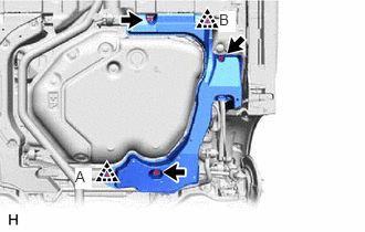
Remove the 3 bolts and clip (A).
Disengage the clip (B) to remove the rear floor side member cover LH.
57627G
3.REMOVE REAR FLOOR SIDE MEMBER COVER RH (for HV Model)
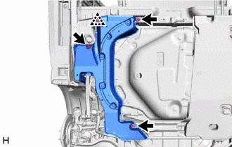
Remove the 3 bolts.
Disengage the clip to remove the rear floor side member cover RH.
57628E
4.REMOVE REAR FLOOR SIDE MEMBER COVER LH (for Gasoline Model)
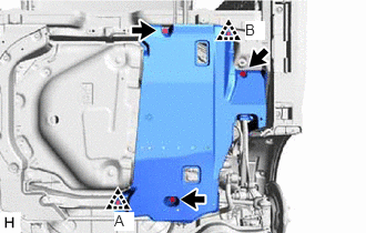
Remove the 3 bolts and clip (A).
Disengage the clip (B) to remove the rear floor side member cover LH.
57627G
5.REMOVE REAR FLOOR SIDE MEMBER COVER RH (for Gasoline Model)
Remove the 3 bolts.
Disengage the clip to remove the rear floor side member cover RH.
48840A
6.REMOVE REAR STABILIZER LINK ASSEMBLY LH
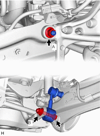
Loosen the nut (A) of the rear stabilizer link assembly LH.
- HINT:
-
If the ball joint turns together with the nut, use a 6 mm hexagon socket wrench to hold the stud bolt.
Loosen the nut (B) of the rear stabilizer link assembly LH.
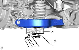
| *a | Wooden Block |
| *b | Jack |
Using a jack and a wooden block, support the rear No. 2 suspension arm assembly.
- NOTICE:
- ·
When jacking up the rear No. 2 suspension arm assembly, be sure to jack it up slowly.
·Make sure to perform this operation with the vehicle kept as low as possible.

Remove the bolt, 2 nuts and rear stabilizer link assembly LH.
48830D
7.REMOVE REAR STABILIZER LINK ASSEMBLY RH
- HINT:
-
Perform the same procedure as for the LH side.
48805
8.REMOVE REAR STABILIZER BAR SUB-ASSEMBLY
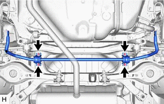
Remove the 4 bolts and rear stabilizer bar sub-assembly from the rear suspension member sub-assembly.