BRAKE CONTROL / DYNAMIC CONTROL SYSTEMS FRONT SPEED SENSOR REMOVAL
CAUTION / NOTICE / HINT
The necessary procedures (adjustment, calibration, initialization or registration) that must be performed after parts are removed and installed, or replaced during front speed sensor removal/installation are shown below.
| Replaced Part or Performed Procedure | Necessary Procedure | Effect/Inoperative Function when Necessary Procedure not Performed | Link |
|---|---|---|---|
|
*: The vehicle height changes because of tire replacement. |
|||
| Tires | Rear television camera assembly optical axis (Back camera position setting)* | Parking Assist Monitor System | ( 202304,999999,_56,_080754,_0596561,RM100000002AX0C,) 202304,999999,_56,_080754,_0596561,RM100000002AX0C,)
|
| Parking assist ECU initialization | Panoramic View Monitor System | (202307,999999,_56,_080754,_0612151,RM100000002CL9H,)
|
|
CAUTION / NOTICE / HINT
- HINT:
- ·
Use the same procedure for the RH side and LH side.
·The following procedure is for the LH side.
·The front speed sensor rotor is a component of the front axle hub sub-assembly. If the front speed sensor rotor is malfunctioning, replace the front axle hub sub-assembly.
PROCEDURE

 1.REMOVE FRONT WHEEL
53876A
2.SEPARATE FRONT FENDER LINER
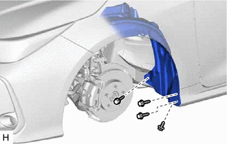
Remove the 4 screws.
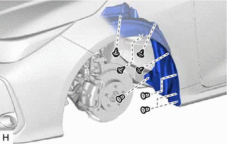
Remove the 4 clips.
Remove the 4 grommets and separate the front fender liner.
89543
3.REMOVE FRONT SPEED SENSOR
Turn back the front fender liner.
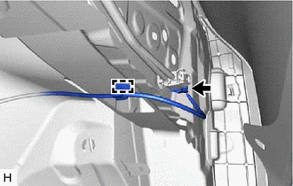
Disconnect the connector.
Disengage the clamp from the vehicle body.
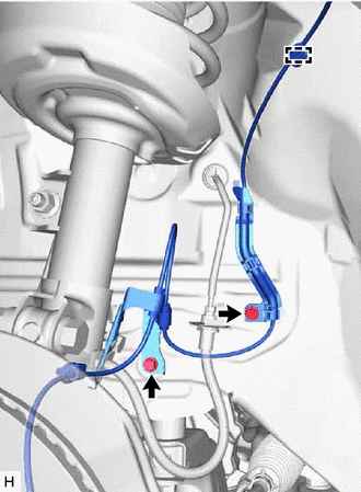
Disengage the clamp from the vehicle body.
Remove the 2 bolts and separate the 2 front speed sensor clamps.
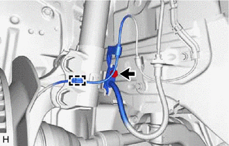
Remove the bolt and separate the front flexible hose and front speed sensor clamp from the front shock absorber assembly.
Disengage the clamp from the front shock absorber assembly.
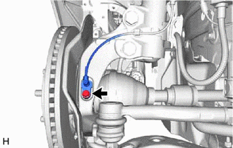
Remove the bolt and front speed sensor from the steering knuckle.
- NOTICE:
- ·
Keep the tip of the front speed sensor and installation hole free of foreign matter.
·Do not rotate or apply excessive force to the front speed sensor when removing it from the steering knuckle. Rotating or applying excessive force may result in damage to the front speed sensor.