AXLE AND DIFFERENTIAL FRONT AXLE HUB ON-VEHICLE INSPECTION
CAUTION / NOTICE / HINT
The necessary procedures (adjustment, calibration, initialization, or registration) that must be performed after parts are removed and installed, or replaced during front axle hub sub-assembly on-vehicle inspection are shown below.
| Replaced Part or Performed Procedure | Necessary Procedure | Effect/Inoperative Function when Necessary Procedure not Performed | Link |
|---|---|---|---|
|
*: The vehicle height changes because of tire replacement. |
|||
| Tires | Rear television camera assembly optical axis (Back camera position setting)* | Parking Assist Monitor System | ( 202304,999999,_56,_080754,_0596561,RM100000002AX0C,) 202304,999999,_56,_080754,_0596561,RM100000002AX0C,)
|
| Parking assist ECU initialization | Panoramic View Monitor System | (202307,999999,_56,_080754,_0612151,RM100000002CL9H,)
|
|
| Replaced Part or Performed Procedure | Necessary Procedure | Effect/Inoperative Function when Necessary Procedure not Performed | Link |
|---|---|---|---|
|
*: The vehicle height changes because of tire replacement. |
|||
| Tires | Rear television camera assembly optical axis (Back camera position setting)* | Parking Assist Monitor System | (202304,999999,_56,_080754,_0596561,RM100000002AX0C,)
|
- HINT:
- ·
Use the same procedure for the RH side and LH side.
·The following procedure is for the LH side.
PROCEDURE

 1.REMOVE FRONT WHEEL
2.SEPARATE FRONT DISC BRAKE CALIPER ASSEMBLY
43512
3.REMOVE FRONT DISC
4.INSPECT FRONT AXLE HUB BEARING LOOSENESS
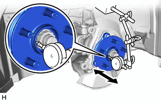
Using a dial indicator with magnetic base, check for looseness near the center of the front axle hub sub-assembly.
- Maximum Looseness:
0.05 mm (0.00196 in.)
- NOTICE:
- ·
Ensure that the dial indicator is set perpendicular to the measurement surface.
·Keep the magnet of the dial indicator away from the front axle hub sub-assembly and front speed sensor.
- HINT:
-
If the looseness exceeds the maximum, replace the front axle hub sub-assembly.
5.INSPECT FRONT AXLE HUB RUNOUT
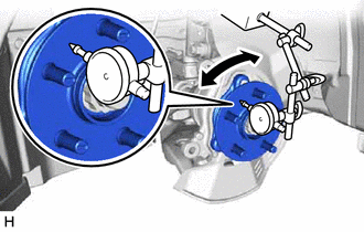
Using a dial indicator with magnetic base, check for runout on the surface of the front axle hub sub-assembly outside the front axle hub bolts.
- Maximum Runout:
0.05 mm (0.00196 in.)
- NOTICE:
- ·
Ensure that the dial indicator is set perpendicular to the measurement surface.
·Make sure to set the tip of the dial indicator towards the outside of the front axle hub bolts.
·Keep the magnet of the dial indicator away from the front axle hub sub-assembly and front speed sensor.
- HINT:
-
If the runout exceeds the maximum, replace the front axle hub sub-assembly.
43512
6.INSTALL FRONT DISC
7.INSTALL FRONT DISC BRAKE CALIPER ASSEMBLY
8.INSTALL FRONT WHEEL