BRAKE (FRONT) FRONT BRAKE REMOVAL
CAUTION / NOTICE / HINT
The necessary procedures (adjustment, calibration, initialization, or registration) that must be performed after parts are removed and installed, or replaced during front brake removal/installation are shown below.
| Replaced Part or Performed Procedure | Necessary Procedure | Effect/Inoperative Function when Necessary Procedure not Performed | Link |
|---|---|---|---|
| Tires | Rear television camera assembly optical axis (Back camera position setting) | Parking Assist Monitor System | ( 202304,999999,_56,_080754,_0596561,RM100000002AX0C,) 202304,999999,_56,_080754,_0596561,RM100000002AX0C,)
|
| Parking assist ECU initialization | Panoramic View Monitor System | (202307,999999,_56,_080754,_0612151,RM100000002CL9H,)
|
- HINT:
-
When the cable is disconnected / reconnected to the auxiliary battery terminal, systems temporarily stop operating. However, each system has a function that completes learning the first time the system is used.
Learning completes when vehicle is driven (for HV Model) Effect/Inoperative Function when Necessary Procedure not Performed Necessary Procedure Link Front Camera System Drive the vehicle straight ahead at 15 km/h (9 mph) or more for 1 second or more. ( 202304,999999,_95,_139716,_0584193,RM1000000029F4C,)
| Replaced Part or Performed Procedure | Necessary Procedure | Effect/Inoperative Function when Necessary Procedure not Performed | Link |
|---|---|---|---|
| Tires | Rear television camera assembly optical axis (Back camera position setting) | Parking Assist Monitor System | (202304,999999,_56,_080754,_0596561,RM100000002AX0C,)
|
- NOTICE:
- ·
Immediately after installing the brake pads, the braking performance may be reduced. Always perform a road test in a safe place while paying attention to the surroundings.
·After replacing the front disc brake pads, the brake pedal may feel soft due to clearance between the front disc brake pads and front disc. Depress the brake pedal several times until the brake pedal feels firm.
·After replacing the front disc brake pads, always perform a road test to check the braking performance and check for vibrations.
- HINT:
- ·
Use the same procedure for the RH side and LH side.
·The following procedure is for the LH side.
PROCEDURE

 1. PRECAUTION (for HV Model)
- NOTICE:
-
After turning the power switch off, waiting time may be required before disconnecting the cable from the negative (-) auxiliary battery terminal. Therefore, make sure to read the disconnecting the cable from the negative (-) auxiliary battery terminal notices before proceeding with work.
2.DISCONNECT CABLE FROM NEGATIVE AUXILIARY BATTERY TERMINAL (for HV Model)
for 8ZR-FXE: Click hereGeneral>MAINTENANCE>8ZR-FXE AUXILIARY BATTERY>REMOVAL202304,999999,_V1,_080956,_0392376,RM100000002ACL7,
for M20F-FXS, M20G-FXS: Click hereGeneral>MAINTENANCE>M20F-FXS, M20G-FXS AUXILIARY BATTERY>REMOVAL202307,999999,_V1,_080956,_0611807,RM100000002CK9K,
3.REMOVE FRONT WHEEL
4.DRAIN BRAKE FLUID
- NOTICE:
-
If brake fluid leaks onto any painted surface, immediately wash it off.
47313J
5.DISCONNECT FRONT FLEXIBLE HOSE
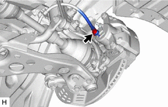
Remove the union bolt and gasket, and disconnect the front flexible hose from the front disc brake cylinder assembly.
47750
6.REMOVE FRONT DISC BRAKE CYLINDER ASSEMBLY
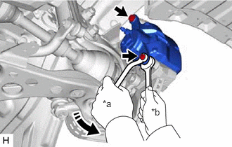
| *a | Turn |
| *b | Hold |
Hold the 2 front disc brake cylinder slide pins and remove the 2 bolts and front disc brake cylinder assembly.
7.REMOVE FRONT DISC BRAKE PAD
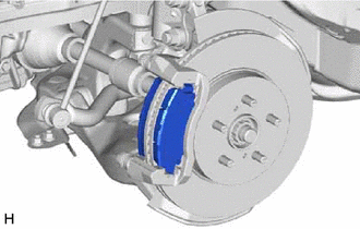
Remove the 2 front disc brake pads from the front disc brake cylinder mounting.
04945
8.REMOVE FRONT DISC BRAKE ANTI-SQUEAL SHIM KIT
9.REMOVE FRONT DISC BRAKE PAD SUPPORT PLATE
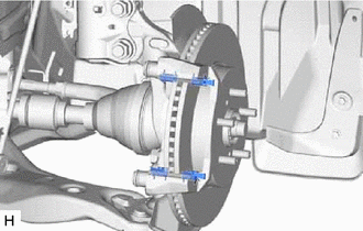
Remove the 4 front disc brake pad support plates from the front disc brake cylinder mounting.
- NOTICE:
-
Each front disc brake pad support plate has a different shape. Be sure to put an identification mark on each front disc brake pad support plate so that it can be reinstalled to its original position.
47715A
10.REMOVE FRONT DISC BRAKE CYLINDER SLIDE PIN
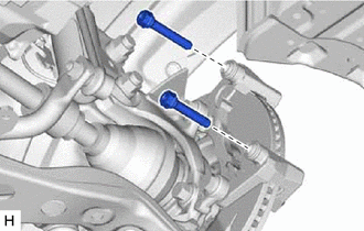
Remove the 2 front disc brake cylinder slide pins from the front disc brake cylinder mounting.
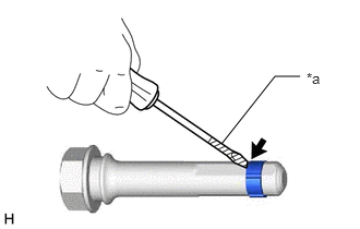
| *a | Protective Tape |
Using a screwdriver with its tip wrapped with protective tape, remove the front disc brake cylinder slide bushing from the front disc brake cylinder slide pin (lower side).
- NOTICE:
-
Do not damage the front disc brake cylinder slide pin.
11.REMOVE FRONT DISC BRAKE BUSHING DUST BOOT
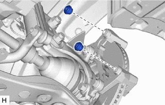
Remove the 2 front disc brake bushing dust boots from the front disc brake cylinder mounting.
47722
12.REMOVE FRONT DISC BRAKE CYLINDER MOUNTING
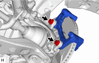
Remove the 2 bolts and front disc brake cylinder mounting from the steering knuckle.
43512
13.REMOVE FRONT DISC

| *a | Matchmark |
Put matchmarks on the front disc and the front axle hub sub-assembly.
Remove the front disc.