POWER DISTRIBUTION POWER INTEGRATION SYSTEM TERMINALS OF ECU
- NOTICE:
-
When disconnecting the cable from the negative (-) auxiliary battery terminal while performing repairs, some systems need to be initialized after the cable is reconnected.
- HINT:
-
When disconnecting and reconnecting the auxiliary battery, there is an automatic learning function that completes learning when the respective system is used.
CHECK MAIN BODY ECU (MULTIPLEX NETWORK BODY ECU) AND POWER DISTRIBUTION BOX ASSEMBLY
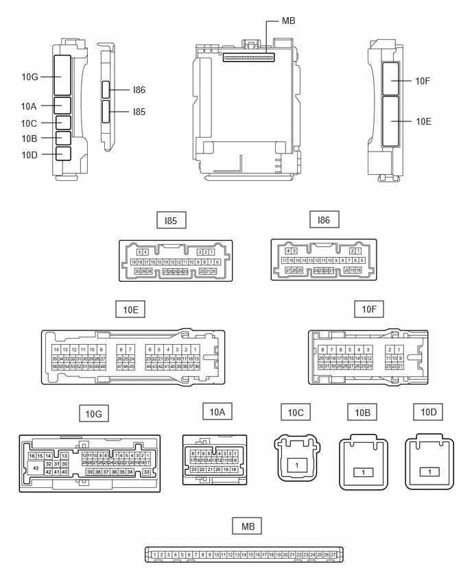
Remove the power distribution box assembly and the main body ECU (multiplex network body ECU).
Connect the power distribution box assembly connectors.
Measure the voltage and resistance according to the value(s) in the table below.
| Terminal No. (Symbol) | Terminal Description | Condition | Specified Condition |
|---|---|---|---|
| MB-13 (GND1) - Body ground | Ground | Always | Below 1 Ω |
| MB-14 (GND2) - Body ground | Ground | Always | Below 1 Ω |
| MB-26 (BECU) - Body ground | Auxiliary battery power supply | Ignition switch off | 11 to 14 V |
| MB-27 (IGR) - Body ground | Ignition power supply (IG signal) | Ignition switch ON | 11 to 14 V |
Install the main body ECU (multiplex network body ECU) to power distribution box assembly.
Measure the voltage according to the value(s) in the table below.
| Terminal No. (Symbol) | Wiring Color | Terminal Description | Condition | Specified Condition |
|---|---|---|---|---|
| 10G-43 - Body ground | B - Body ground | Rear window defogger signal (output) | Rear window defogger switch off | Below 1 V |
| Rear window defogger switch on | 11 to 14 V | |||
| 10G-13 - Body ground | B - Body ground*1
GR - Body ground*2 R - Body ground*5 |
Back-up light output | Ignition switch ON, shift position is not R | Below 1 V |
| Ignition switch ON, shift position is R | 11 to 14 V | |||
| 10F-11 - Body ground | B - Body ground*1
LA-R - Body ground*2 R - Body ground*5, *6 |
DOME CUT relay output | Always | 11 to 14 V |
| 10G-24 - Body ground | R - Body ground | |||
| 10E-6 - Body ground*3 | P - Body ground*1
LG - Body ground*2 |
Mirror heater drive voltage (output) | Rear window defogger switch off | Below 1 V |
| Rear window defogger switch on | 11 to 14 V | |||
| 10G-15 - Body ground | L - Body ground*1, *6
G - Body ground*2 |
Tail light output | Tail light not illuminated | Below 1 V |
| Tail light illuminated | 11 to 14 V | |||
| 10A-20 - Body ground | L - Body ground*1, *6
LG - Body ground*2 |
Tail light not illuminated | Below 1 V | |
| Tail light illuminated | 11 to 14 V | |||
| 10G-7 - Body ground*4 | R - Body ground | Front fog light output | Tail light illuminated, front fog light switch off | 11 to 14 V |
| Tail light illuminated, front fog light switch on | Below 1 V | |||
| 10G-29 - Body ground | P - Body ground*1
BR - Body ground*2 B - Body ground*6 |
Rear fog light output | Tail light illuminated, rear fog light switch off | Below 1 V |
| Tail light illuminated, rear fog light switch on | 11 to 14 V |
*1: for TFTM Made
*2: for GTMC Made
*3: w/ Mirror Heater
*4: w/ Front Fog Light
*5: for ALLION
*6: for M20C-FKS, M20F-FXS