DOOR LOCK WIRELESS DOOR LOCK CONTROL SYSTEM(w/o Smart Entry and Start System) No Answer-Back
DESCRIPTION
In some cases, wireless door lock control functions are normal but the hazard warning light answer-back function does not operate. In such cases, hazard warning light signal outputs from the main body ECU (multiplex network body ECU) may be malfunctioning.
WIRING DIAGRAM
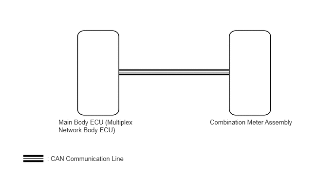
CAUTION / NOTICE / HINT
- NOTICE:
-
The wireless door lock control system uses the CAN communication system. Inspect the communication function by following How to Proceed with Troubleshooting. Troubleshoot the wireless door lock control system after confirming that the communication system is functioning properly.
PROCEDURE
Select the setting by referring to the table below.
- Wireless Door Lock
-
Tester Display Description Default Setting ECU Hazard Answer Back Function Function that flashes the hazard warning lights once when the doors are locked by wireless operation and twice when the doors are unlocked by wireless operation Enable $00:Disable,$01:Enable Main body ECU (Multiplex network body ECU) - 50006 1
- Result:
Result Proceed to Hazard Answer Back is Enable A Hazard Answer Back is Disable B
A
B
Check the wireless door lock control function using the door control transmitter assembly.
- Result:
Result Proceed to Wireless door lock/unlock operates properly A Wireless door lock/unlock does not operate properly B
A
B
Read the Data List according to the display on the GTS.
- Body Electrical > Main Body > Data List
-
Tester Display Measurement Item Range Normal Condition Diagnostic Note FR Door Lock Position Switch Status Front door RH unlock detection switch signal Lock or Unlock Lock: Front door RH locked
Unlock: Front door RH unlocked- FL Door Lock Position Switch Status Front door LH unlock detection switch signal Lock or Unlock Lock: Front door LH locked
Unlock: Front door LH unlocked- RR Door Lock Position Switch Status Rear door RH unlock detection switch signal Lock or Unlock Lock: Rear door RH locked
Unlock: Rear door RH unlocked- RL Door Lock Position Switch Status Rear door LH unlock detection switch signal Lock or Unlock Lock: Rear door LH locked
Unlock: Rear door LH unlocked-
- Body Electrical > Main Body > Data List
-
Tester Display FR Door Lock Position Switch Status FL Door Lock Position Switch Status RR Door Lock Position Switch Status RL Door Lock Position Switch Status - 50003 449 20,21,22,23
- OK:
The GTS display changes correctly in response to the lock/unlock operation.
- Result:
Proceed to OK NG
OK
NG
Check that the hazard warning lights blink when the hazard warning signal switch is pressed.
- OK:
Hazard warning lights blink.
- Result:
Proceed to OK NG
OK
NG