THEFT DETERRENT / KEYLESS ENTRY DIGITAL KEY SYSTEM Digital Key cannot be Canceled
DESCRIPTION
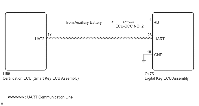
After the ignition switch was turned ON using the electrical key transmitter sub-assembly, it is possible to cancel the digital key system. If it is not possible to cancel the digital key system after the ignition switch was turned ON using the electrical key transmitter sub-assembly, there may be a malfunction in the communication system between the certification ECU (smart key ECU assembly) and the digital key ECU assembly.
WIRING DIAGRAM
CAUTION / NOTICE / HINT
- NOTICE:
- ·
Before performing troubleshooting of the vehicle, refer to Precautions for Inspection or Registration to check for a cause of the malfunction which is not related to vehicle settings or vehicle components.
·Make sure that no DTCs are output. If any DTCs are output, proceed to Diagnostic Trouble Code Chart.
·Before replacing the certification ECU (smart key ECU assembly) or digital key ECU assembly, refer to Service Bulletin.
PROCEDURE
Select the setting by referring to the table below.
- Entry & Start
-
Tester Display Description Default Setting ECU Auto Entry Function by Digital Key Function that enables or disables the digital key system Normal $00:Normal,$01:Cancel Certification ECU (Smart key ECU assembly) - 50006 17
- OK:
The digital key system can be canceled
- Result:
Proceed to OK NG
OK
NG
Check the vehicle specification.
- Result:
Result Proceed to w/ Audio and Visual System A w/ Navigation System B
A
B
Using an oscilloscope, check the waveform.
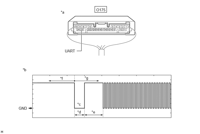
| *a | Component with harness connected
(Digital Key ECU Assembly) |
*b | Waveform |
| *c | Wakeup signal from digital key ECU assembly | *d | Approximately 15 ms. |
| *e | 15 to 50 ms. | *f | Before door lock/unlock operation using digital key |
| *g | After door lock/unlock operation using digital key | - | - |
- NOTICE:
-
The waveform shown in the illustration is an example for reference only. Noise, chattering, etc. are not shown.
- OK:
Tester Connection Condition Tool Setting Specified Condition O175-23 (UART) - Body ground All of the following conditions are met:
·Ignition switch off
·Door lock/unlock operation has been not performed via digital key → performed
2 V/DIV., 20 ms./DIV. Pulse generation
(See waveform)
- Result:
Result Proceed to OK (Normal Waveform) A NG (No Wakeup Signal) B NG (Normal Waveform Not Output) C NG (Stuck Low) D
A
B
C
D
Replace the digital key ECU assembly with a new one.
- HINT:
-
Refer to Service Bulletin.
- Result:
Proceed to NEXT
NEXT
Register the digital key code to the digital key ECU assembly.
- HINT:
-
Refer to Service Bulletin.
- Result:
Proceed to NEXT
NEXT
Register the owner key using the original digital key.
- HINT:
-
Refer to the digital key application.
- Result:
Proceed to NEXT
NEXT
Use the electrical key transmitter sub-assembly and turn the ignition switch to ON.
- NOTICE:
-
The digital key system can be canceled only after the ignition switch was turned ON using the electrical key transmitter sub-assembly.
Use the multi-display and check the customize settings of the digital key system.
- OK:
The digital key system can be canceled
- Result:
Proceed to OK NG
OK
NG
Disconnect the O175 digital key ECU assembly connector.
Measure the voltage according to the value(s) in the table below.
- Standard Voltage:
Tester Connection Condition Specified Condition O175-23 (UART) - Body ground Ignition switch off 11 to 14 V
- Result:
Proceed to OK NG
OK
NG