NR Series ENGINE MECHANICAL CYLINDER HEAD DISASSEMBLY
CAUTION / NOTICE / HINT
The necessary procedures (adjustment, calibration, initialization or registration) that must be performed after parts are removed and installed, or replaced during cylinder head removal/installation are shown below.
| Replaced Part or Performed Procedure | Necessary Procedure | Effect/Inoperative Function when Necessary Procedure not Performed | Link |
|---|---|---|---|
| Replacement of ECM | Perform Vehicle Identification Number (VIN) or frame number registration | DTC is stored | ( 201906,999999,_51,_080777,_0393969,RM100000001I1RD,) 201906,999999,_51,_080777,_0393969,RM100000001I1RD,)
|
1.
Reset memory 2.
Deceleration sensor zero point calibration 3.
CVT oil pressure calibration |
·
Large shift shock ·
Deterioration of fuel efficiency |
(201906,999999,_52,_080728,_0392261,RM100000001HP98,)
|
|
| Code registration (Immobiliser system) | Engine start | See Service Bulletin for the registration method | |
| Replacement of piston ring | Clear Heavy Knock History | - | (201906,999999,_51,_080777,_0393969,RM100000001I1RE,)
|
·
Replacement of throttle body with motor assembly ·
Replacement of engine assembly ·
Replacement of cylinder head sub-assembly ·
Replacement of camshaft (for intake or exhaust camshaft) ·
Replacement of camshaft timing gear assembly ·
Replacement of camshaft timing exhaust gear assembly ·
Replacement of mass air flow meter sub-assembly ·
Replacement of fuel injector assembly ·
Replacement of fuel pump (for high pressure side) ·
Replacement of engine coolant temperature sensor ·
Replacement of spark plug ·
Replacement of ignition coil assembly ·
Gas leaks from exhaust system ·
Replacement of knock control sensor ·
Replacement of fuel delivery pipe (fuel pressure sensor) |
Inspection After Repair | ·
Poor idle, etc. ·
Engine start function, etc. |
(201906,999999,_51,_080777,_0393969,RM100000001I1RE,)
|
| Replacement of starter assembly | Clear the number of starter operations | Stop and Start System | (201906,999999,_51,_080774,_0393362,RM100000001HXHH,)
|
| Replacement of battery | Integrated current value initialization | ||
| Replacement of continuously variable transaxle assembly | Air bleed the oil pump with motor assembly | Stop and Start System | (201906,999999,_51,_080774,_0393362,RM100000001HXHH,)
|
1.
Reset memory 2.
Deceleration sensor zero point calibration 3.
CVT oil pressure calibration |
·
Large shift shock ·
Deterioration of fuel efficiency |
(201906,999999,_52,_080728,_0392261,RM100000001HP98,)
|
|
| Replacement of CVT fluid | Air bleed the oil pump with motor assembly | Stop and Start System | (201906,999999,_51,_080774,_0393362,RM100000001HXHH,)
|
| ATF thermal degradation estimate reset | The value of the Data List item "ATF Thermal Degradation Estimate" is not estimated correctly | (201906,999999,_52,_080728,_0392261,RM100000001HP98,)
|
|
| Tires | Rear television camera assembly optical axis (Back camera position setting) | Parking Assist Monitor System | (202304,999999,_56,_080754,_0596561,RM100000002AX0C,)
|
| Suspension parts | Rear television camera assembly optical axis (Back camera position setting) | Parking Assist Monitor System | (202304,999999,_56,_080754,_0596561,RM100000002AX0C,)
|
| Front wheel alignment adjustment | ·
Perform "Reset Memory" ·
Perform acceleration sensor zero point calibration and store system information memorization |
·
VSC is disabled or malfunctions ·
DTCs are stored ·
Slip indicator light illuminates ·
ABS warning light illuminates |
(202304,999999,_54,_080770,_0599814,RM100000002BA8F,)
|
- HINT:
-
When the cable is disconnected / reconnected to the battery terminal, systems temporarily stop operating. However, each system has a function that completes learning the first time the system is used.
Learning completes when vehicle is driven Effect/Inoperative Function when Necessary Procedure not Performed Necessary Procedure Link Stop and Start System Idle the engine for approximately 5 to 60 minutes or drive the vehicle until stop and start control is permitted ( 201906,999999,_51,_080774,_0393362,RM100000001HXHC,)
Pre-collision System Perform steering sensor zero point calibration ( 202304,999999,_95,_139716,_0601175,RM100000002BFOE,)
Lane Tracing Assist System
PROCEDURE

 13711
1.REMOVE INTAKE VALVE
13711
1.REMOVE INTAKE VALVE
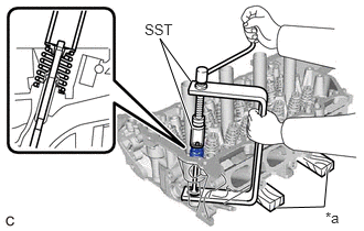
| *a | Wooden Block |
Using SST and wooden blocks, compress the intake valve compression spring and remove the 8 valve spring retainer locks.
- SST
- 09202-70020
09202-00021
- HINT:
-
Arrange the removed parts in such a way that they can be reinstalled to their original locations.
Remove the 8 valve spring retainers, 8 intake valve compression springs and 8 intake valves from the cylinder head sub-assembly.
- HINT:
-
Arrange the removed parts in such a way that they can be reinstalled to their original locations.
13715
2.REMOVE EXHAUST VALVE
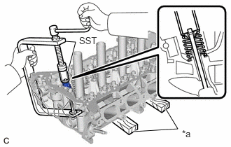
| *a | Wooden Block |
Using SST and wooden blocks, compress the exhaust valve compression spring and remove the 8 valve spring retainer locks.
- SST
- 09202-70020
09202-00021
- HINT:
-
Arrange the removed parts in such a way that they can be reinstalled to their original locations.
Remove the 8 valve spring retainers, 8 exhaust valve compression springs and 8 exhaust valves from the cylinder head sub-assembly.
- HINT:
-
Arrange the removed parts in such a way that they can be reinstalled to their original locations.
13711E
3.REMOVE INTAKE VALVE STEM OIL SEAL
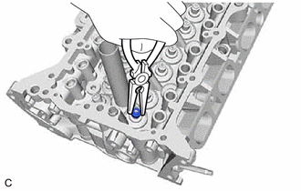
Using needle-nose pliers, remove the 8 intake valve stem oil seals.
13715A
4.REMOVE EXHAUST VALVE STEM OIL SEAL
- HINT:
-
Use the same procedure as for the intake side.
13734
5.REMOVE VALVE SPRING SEAT
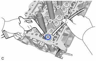
Using compressed air and a magnet hand, remove the 16 valve spring seats by blowing air onto them.
11117E
6.REMOVE NO. 1 STRAIGHT SCREW PLUG
- NOTICE:
-
If coolant leaks from a No. 1 straight screw plug or a plug is corroded, replace it.
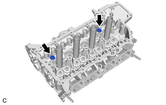
Using a 6 mm hexagon wrench, remove the 2 No. 1 straight screw plugs from the cylinder head sub-assembly.
11117F
7.REMOVE NO. 2 STRAIGHT SCREW PLUG
- NOTICE:
-
If coolant leaks from a No. 2 straight screw plug or a plug is corroded, replace it.
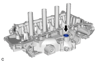
Using a 10 mm hexagon wrench, remove the No. 2 straight screw plug and cylinder head screw plug gasket from the cylinder head sub-assembly.
11117G
8.REMOVE NO. 3 STRAIGHT SCREW PLUG
- NOTICE:
-
If coolant leaks from a No. 3 straight screw plug or the plug is corroded, replace it.
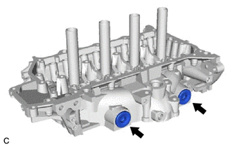
Using a 14 mm hexagon wrench, remove the 2 No. 3 straight screw plugs and 2 No. 2 cylinder head screw plug gaskets from the cylinder head sub-assembly.