RM3660EC _59 Vehicle Exterior _080784 LIGHTING (EXT) _0600055 LIGHTING SYSTEM(for NR Series Engine) J

LIGHTING (EXT)  LIGHTING SYSTEM(for NR Series Engine)  Rear Fog Light Circuit  


DESCRIPTION

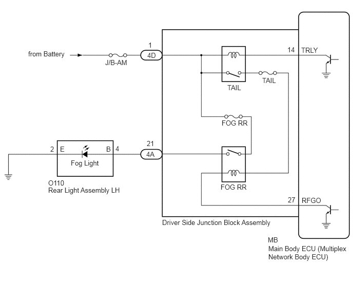
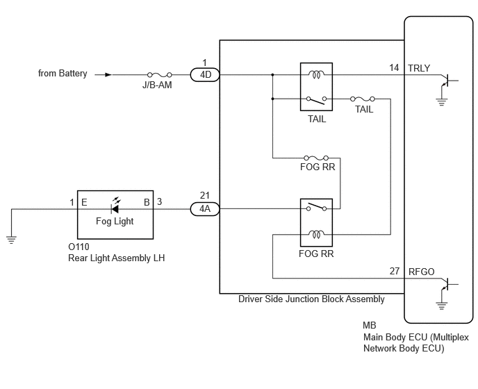
The main body ECU (multiplex network body ECU) controls the rear fog light.

WIRING DIAGRAM

for TFTM Made

E386591E39
0.573,1.01 1.469,1.74 0.896,0.729 10 false from Battery 2.135,1.188 2.719,1.385 0.583,0.198 10 false J/B-AM 1.021,3.781 2.719,4.229 1.698,0.448 10 false Rear Light Assembly LH 2.354,2.938 2.656,3.135 0.302,0.198 10 false 3 1.042,2.948 1.344,3.146 0.302,0.198 10 false 1 2.156,2.948 2.458,3.146 0.302,0.198 10 false B 1.219,2.948 1.521,3.146 0.302,0.198 10 false E 2.99,3.042 3.542,3.25 0.552,0.208 10 false 4A 3,2.844 3.552,3.052 0.552,0.208 10 false 21 3,1.031 3.552,1.24 0.552,0.208 10 false 4D 3.031,0.854 3.583,1.063 0.552,0.208 10 false 1 4.615,1.698 5.167,1.906 0.552,0.208 10 false TAIL 4.5,2.417 5.052,2.625 0.552,0.208 10 false FOG RR 6.115,0.938 6.667,1.146 0.552,0.208 10 false TRLY 5.833,0.927 6.385,1.135 0.552,0.208 10 false 14 6.125,3.99 6.677,4.198 0.552,0.208 10 false RFGO 5.844,3.979 6.396,4.188 0.552,0.208 10 false 27 5.438,4.792 5.99,5 0.552,0.208 10 false MB 5.448,4.969 7.104,5.396 1.656,0.427 10 false Main Body ECU (Multiplex Network Body ECU) 3.573,4.396 6.51,4.656 2.938,0.26 10 false Driver Side Junction Block Assembly 1.438,3.229 2.281,3.438 0.844,0.208 10 false Fog Light 5.323,1.552 5.875,1.76 0.552,0.208 10 false TAIL 4.479,3.719 5.031,3.927 0.552,0.208 10 false FOG RR 1.021,3.615 1.573,3.823 0.552,0.208 10 false O110


for GTMC Made


E386591E22
0.573,1.01 1.469,1.74 0.896,0.729 10 false from Battery 2.135,1.188 2.719,1.385 0.583,0.198 10 false J/B-AM 0.979,3.635 1.531,3.844 0.552,0.208 10 false O110 0.979,3.781 2.677,4.229 1.698,0.448 10 false Rear Light Assembly LH 2.344,2.938 2.646,3.135 0.302,0.198 10 false 4 1.021,2.948 1.323,3.146 0.302,0.198 10 false 2 2.156,2.948 2.458,3.146 0.302,0.198 10 false B 1.219,2.948 1.521,3.146 0.302,0.198 10 false E 2.969,3.052 3.521,3.26 0.552,0.208 10 false 4A 2.979,2.833 3.531,3.042 0.552,0.208 10 false 21 2.99,1.042 3.542,1.25 0.552,0.208 10 false 4D 3.01,0.833 3.563,1.042 0.552,0.208 10 false 1 4.615,1.698 5.167,1.906 0.552,0.208 10 false TAIL 4.5,2.417 5.052,2.625 0.552,0.208 10 false FOG RR 6.115,0.938 6.667,1.146 0.552,0.208 10 false TRLY 5.833,0.927 6.385,1.135 0.552,0.208 10 false 14 6.125,3.99 6.677,4.198 0.552,0.208 10 false RFGO 5.844,3.979 6.396,4.188 0.552,0.208 10 false 27 5.438,4.792 5.99,5 0.552,0.208 10 false MB 5.448,4.969 7.104,5.396 1.656,0.427 10 false Main Body ECU (Multiplex Network Body ECU) 3.292,4.438 6.229,4.698 2.938,0.26 10 false Driver Side Junction Block Assembly 1.438,3.229 2.281,3.438 0.844,0.208 10 false Fog Light 5.323,1.552 5.875,1.76 0.552,0.208 10 false TAIL 4.479,3.719 5.031,3.927 0.552,0.208 10 false FOG RR


CAUTION / NOTICE / HINT

NOTICE:
·

Inspect the fuses for circuits related to this system before performing the following procedure.

·

Before replacing the main body ECU (multiplex network body ECU), refer to Service Bulletin.


PROCEDURE

1.CHECK OPERATION (TAILLIGHTS)
a.

Check the operation of the taillights.

OK:

Taillights operate normally.


Result:
Proceed to
OK
NG


OK

2.PERFORM ACTIVE TEST USING GTS

NG

2.PERFORM ACTIVE TEST USING GTS
a.

Connect the GTS to the DLC3.


b.

Turn the ignition switch to ON.


c.

Turn the GTS on.


d.

Enter the following menus: Body Electrical / Main Body / Active Test.


e.

Perform the Active Test according to the display on the GTS.

Body Electrical > Main Body > Active Test
Tester Display Measurement Item Control Range Diagnostic Note
Rear Fog Light Relay Rear fog lights OFF or ON Light control switch in tail position
Body Electrical > Main Body > Active Test
Tester Display
Rear Fog Light Relay
50004 123 17
OK:

Rear fog light relay operates. (Rear fog lights come on.)


Result:
Proceed to
OK
NG


OK

NG

3.CONFIRM MODEL
3.CONFIRM MODEL
a.

Choose the model to be inspected.


Result:
Result Proceed to
for TFTM Made A
for GTMC Made B


A

4.CHECK HARNESS AND CONNECTOR (REAR LIGHT ASSEMBLY - DRIVER SIDE JUNCTION BLOCK ASSEMBLY AND BODY GROUND)

B

6.CHECK HARNESS AND CONNECTOR (REAR LIGHT ASSEMBLY - DRIVER SIDE JUNCTION BLOCK ASSEMBLY AND BODY GROUND)
4.CHECK HARNESS AND CONNECTOR (REAR LIGHT ASSEMBLY - DRIVER SIDE JUNCTION BLOCK ASSEMBLY AND BODY GROUND)
a.

Disconnect the 4A driver side junction block assembly connector.


b.

Disconnect the O110 rear light assembly LH connector.


c.

Measure the resistance according to the value(s) in the table below.

Standard Resistance:
Tester Connection Condition Specified Condition
O110-3 (B) - 4A-21 Always Below 1 Ω
O110-3 (B) or 4A-21 - Body ground Always 10 kΩ or higher
O110-1 (E) - Body ground Always Below 1 Ω


Result:
Proceed to
OK
NG


OK

5.INSPECT DRIVER SIDE JUNCTION BLOCK ASSEMBLY

NG

REPAIR OR REPLACE HARNESS OR CONNECTOR

5.INSPECT DRIVER SIDE JUNCTION BLOCK ASSEMBLY
E345461C14
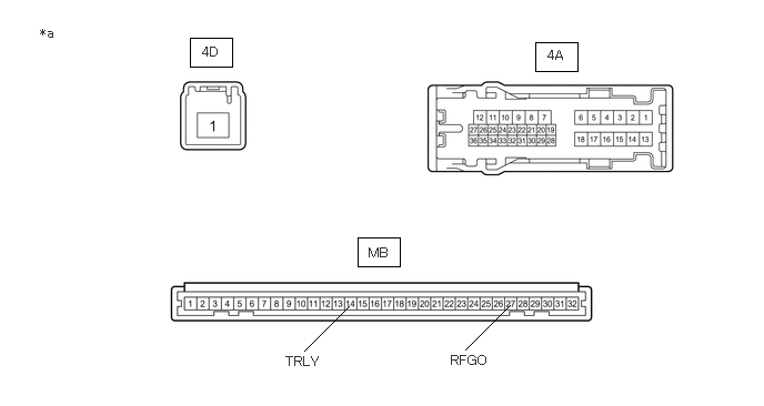
1.781,0.354 2.177,0.625 0.396,0.271 5.021,0.396 5.417,0.667 0.396,0.271 3.354,2.229 3.75,2.5 0.396,0.271 2.854,3.292 3.271,2.875 false 4.365,3.281 4.781,2.865 false 1.896,0.417 2.271,0.688 0.375,0.271 10 false 4D 5.135,0.448 5.51,0.719 0.375,0.271 10 false 4A 3.458,2.302 3.833,2.573 0.375,0.271 10 false MB 2.677,3.323 3.219,3.594 0.542,0.271 10 false TRLY 4.229,3.313 4.771,3.583 0.542,0.271 10 false RFGO 0.375,0.24 0.75,0.51 0.375,0.271 10 false *a
*a Component without harness connected
(Driver Side Junction Block Assembly)
- -


a.

Remove the main body ECU (multiplex network body ECU) from the driver side junction block assembly.

Click herePower Source / Network>POWER DISTRIBUTION>MAIN BODY ECU>REMOVAL


b.

Connect a positive (+) lead from the battery to terminal 4D-1.


c.

Connect a negative (-) lead from the battery to terminal MB-14 (TRLY) and MB-27 (RFGO).


d.

Measure the voltage according to the value(s) in the table below.

Standard Voltage:
Tester Connection Condition Specified Condition
4A-21 - Battery negative (-) terminal Always 11 to 14 V


Result:
Proceed to
OK
NG


OK

NG

6.CHECK HARNESS AND CONNECTOR (REAR LIGHT ASSEMBLY - DRIVER SIDE JUNCTION BLOCK ASSEMBLY AND BODY GROUND)
a.

Disconnect the 4A driver side junction block assembly connector.


b.

Disconnect the O110 rear light assembly LH connector.


c.

Measure the resistance according to the value(s) in the table below.

Standard Resistance:
Tester Connection Condition Specified Condition
O110-4 (B) - 4A-21 Always Below 1 Ω
O110-4 (B) or 4A-21 - Body ground Always 10 kΩ or higher
O110-2 (E) - Body ground Always Below 1 Ω


Result:
Proceed to
OK
NG


OK

7.INSPECT DRIVER SIDE JUNCTION BLOCK ASSEMBLY

NG

REPAIR OR REPLACE HARNESS OR CONNECTOR

7.INSPECT DRIVER SIDE JUNCTION BLOCK ASSEMBLY
E345461C14
1.781,0.354 2.177,0.625 0.396,0.271 5.021,0.396 5.417,0.667 0.396,0.271 3.354,2.229 3.75,2.5 0.396,0.271 2.854,3.292 3.271,2.875 false 4.365,3.281 4.781,2.865 false 1.896,0.417 2.271,0.688 0.375,0.271 10 false 4D 5.135,0.448 5.51,0.719 0.375,0.271 10 false 4A 3.458,2.302 3.833,2.573 0.375,0.271 10 false MB 2.677,3.323 3.219,3.594 0.542,0.271 10 false TRLY 4.229,3.313 4.771,3.583 0.542,0.271 10 false RFGO 0.375,0.24 0.75,0.51 0.375,0.271 10 false *a
*a Component without harness connected
(Driver Side Junction Block Assembly)
- -


a.

Remove the main body ECU (multiplex network body ECU) from the driver side junction block assembly.

Click herePower Source / Network>POWER DISTRIBUTION>MAIN BODY ECU>REMOVAL


b.

Connect a positive (+) lead from the battery to terminal 4D-1.


c.

Connect a negative (-) lead from the battery to terminal MB-14 (TRLY) and MB-27 (RFGO).


d.

Measure the voltage according to the value(s) in the table below.

Standard Voltage:
Tester Connection Condition Specified Condition
4A-21 - Battery negative (-) terminal Always 11 to 14 V


Result:
Proceed to
OK
NG


OK

NG