BRAKE CONTROL / DYNAMIC CONTROL SYSTEMS ELECTRONICALLY CONTROLLED BRAKE SYSTEM(for Gasoline Model (NR Series)) C137BA3 Brake System Control Module "A" System Voltage System Voltage High
DESCRIPTION
If a malfunction is detected in the power supply circuit, the skid control ECU (brake actuator assembly) stores this DTC and the fail-safe function prohibits ABS operation.
This DTC is stored when the +BS terminal voltage deviates due to a malfunction in a power supply or charging system circuit such as the battery or alternator circuit, etc.
| DTC No. | Detection Item | DTC Detection Condition | Trouble Area |
|---|---|---|---|
| C137BA3 | Brake System Control Module "A" System Voltage System Voltage High | +BS terminal voltage is more than 16.5 V for 1 second or more. | ·
Power source circuit ·
Internal power supply circuit of the skid control ECU (brake actuator assembly) |
WIRING DIAGRAM
CAUTION / NOTICE / HINT
- NOTICE:
-
After replacing the skid control ECU (brake actuator assembly), perform acceleration sensor zero point calibration and store system information memorization.
PROCEDURE
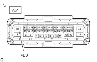
| *a | Front view of wire harness connector
(to Skid Control ECU (Brake Actuator Assembly)) |
Make sure that there is no looseness at the locking part and the connecting part of the connector.
- OK:
The connector is securely connected.
Disconnect the A51 skid control ECU (brake actuator assembly) connector.
Check both the connector case and the terminals for deformation and corrosion.
- OK:
No deformation or corrosion.
Measure the voltage according to the value(s) in the table below.
- Standard Voltage:
Tester Connection Condition Specified Condition A51-30 (+BS) - Body ground Always 11 to 14 V
- Result:
Proceed to OK NG
OK
NG