AUDIO / VIDEO AUDIO AND VISUAL SYSTEM(for 10.25 Inch Display) OPERATION CHECK
CHECK SPEAKER
- HINT:
-
For information on how to start diagnosis and transition to each screen, refer to Click hereAudio / Visual / Telematics>AUDIO / VIDEO>AUDIO AND VISUAL SYSTEM (for 10.25 Inch Display)>DIAGNOSIS SYSTEM202304,999999,_56,_080751,_0599626,RM100000002B8WL,
Enter diagnostic mode.
Start diagnosis and display the "Service Menu" screen.
Select "Failure Diagnosis" on the "Service Menu" screen to display the failure diagnosis screen.
Select "System Check" of the failure diagnosis screen to display the system check mode screen.
Speaker check
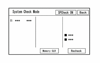
Select "SPCheck ON" from the "System Check Mode" screen.
Check that each speaker outputs sound.
- HINT:
- ·
"SPCheck OFF" is displayed during the speaker check.
·Sound can be heard from the speakers around the vehicle in order beginning from the speaker on the front side.
·The sounding order during speaker check cannot be adjusted.
·More than one speaker may sound simultaneously depending on the speaker wiring.
·If sound is not output from a speaker, check the wire harness between the radio and display receiver assembly and each speaker for a malfunction.
Sound stops when any of the following conditions are met:
"SPCheck OFF" is selected.
The screen is changed to another screen.
Diagnostic mode is turned off.
The ignition switch is turned off.
CHECK PANEL SWITCH
- HINT:
-
For enter diagnostic mode and screen transition, refer toAudio / Visual / Telematics>AUDIO / VIDEO>AUDIO AND VISUAL SYSTEM (for 10.25 Inch Display)>DIAGNOSIS SYSTEM202304,999999,_56,_080751,_0599626,RM100000002B8WL,
Enter diagnostic mode.
Enter diagnostic mode.
Select "Function Check/Setting I" from the "Service Menu" screen.
Select "Panel&Steering Switch" on the "Function Check/Setting I" screen to display the "Panel Switch Check Mode" screen.
Panel Switch Check Mode
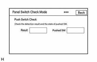
Operate each switch and check that the switch conditions are correctly displayed.
| Display | Content |
|---|---|
| *a: Switch condition | "Pushed" is displayed when any switch is pushed. |
| *b: Name of switch pushed | Name of switch pushed at once is displayed. |
| *c: Communication method | The steering pad switch assembly method of communication is displayed. |
- HINT:
- ·
Do not push any switch for 10 seconds or more as doing so may cancel diagnostic mode.
·If the result of a switch check for the radio and display receiver assembly is abnormal, it can be suspected that the radio and display receiver assembly is malfunctioning.
·If the result of a switch check for the steering pad switch assembly is abnormal, it is necessary to perform an inspection of the steering pad switch assembly and spiral cable sub-assembly.
Steering pad switch assembly: Click hereSteering>STEERING COLUMN>STEERING PAD SWITCH>INSPECTION202304,999999,_55,_080762,_0391591,RM100000002GK28,
Spiral cable sub-assembly: Click hereVehicle Interior>SUPPLEMENTAL RESTRAINT SYSTEMS>SPIRAL CABLE>INSPECTION202304,999999,_58,_080741,_0392903,RM100000002B7U0,
CHECK TOUCH SWITCH
- HINT:
-
For enter diagnostic mode and screen transition, refer toAudio / Visual / Telematics>AUDIO / VIDEO>AUDIO AND VISUAL SYSTEM (for 10.25 Inch Display)>DIAGNOSIS SYSTEM202304,999999,_56,_080751,_0599626,RM100000002B8WL,
Enter diagnostic mode.
Enter diagnostic mode.
Select "Function Check/Setting" from the "Service Menu" screen.
Select "Touch Switch Check" on the "Function Check/Setting I" screen to display the "Touch Switch Check" screen.
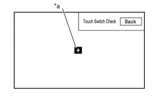
| *a | "+" mark |
Touch Switch Check
Touch the display anywhere in the open area to perform the check when the "Touch Switch Check" screen is displayed.
A "+" mark is displayed where the display is touched.
- HINT:
- ·
The "+" mark remains on the display even after your finger is removed.
·If the result of the touch switch check is abnormal, it can be suspected that the multi-display is malfunctioning.
CHECK MICROPHONE
- HINT:
-
For enter diagnostic mode and screen transition, refer toAudio / Visual / Telematics>AUDIO / VIDEO>AUDIO AND VISUAL SYSTEM (for 10.25 Inch Display)>DIAGNOSIS SYSTEM202304,999999,_56,_080751,_0599626,RM100000002B8WL,
Enter diagnostic mode.
Enter diagnostic mode.
Select "Function Check/Setting" from the "Service Menu" screen.
Select "Microphone Check" on the "Function Check/Setting I" screen to display the microphone check screen.
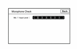
Microphone Check
| Display | Content |
|---|---|
| *a: Microphone 1 input level meter | Displays the input level in 8 steps for microphone 1 |
Speak to the microphone and check that the microphone input level meter changes according to the input level.
- HINT:
-
The microphone input level is updated every 0.1 seconds.
- OK:
The microphone input level changes
CHECK SYSTEM SENSORS
- HINT:
-
For enter diagnostic mode and screen transition, refer toAudio / Visual / Telematics>AUDIO / VIDEO>AUDIO AND VISUAL SYSTEM (for 10.25 Inch Display)>DIAGNOSIS SYSTEM202304,999999,_56,_080751,_0599626,RM100000002B8WL,
Enter diagnostic mode.
Enter diagnostic mode.
Select "Function Check/Setting" from the "Service Menu" screen.
Select "System Sensors Check" on the "Function Check/Setting I" screen to display the "System Sensors Check" screen.
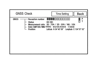
System Sensors Check
| Display | Content | ||
|---|---|---|---|
| Reception number | Displays reception condition of the satellites used to determine vehicle position | Blue: P (In use) | System is using GNSS signal for location. |
| Yellow: T (Receiving) | System is tracking GNSS signal for location. | ||
| No color: Not in use | ·
When "Data collected, unused measurement" notification is received via the GNSS receiver ·
When "searching" notification is received from the GNSS receiver |
||
| Status | Displays reception status of the satellites used to determine vehicle position | OK (3D) | 3-dimensional location method is being used. |
| OK (2D) | 2-dimensional location method is being used. | ||
| NG | Location data cannot be used. | ||
| error | Reception error has occurred. | ||
| - | Any other state. | ||
| Measurement ratio | Displays the ratio of satellites performing measurements | 3D | The ratio of satellites performing 3D positioning is displayed. |
| 2D | The ratio of satellites performing 2D positioning is displayed. | ||
| NG | The ratio of satellites not performing measurement is displayed. | ||
| Date | Date/time information obtained from GNSS signals is displayed in Greenwich Mean Time (GMT). | ||
| Position | Latitude and longitude information on current position is displayed. | ||
- HINT:
-
This screen is updated once per second.
GNSS TIME SETTING
- HINT:
-
For enter diagnostic mode and screen transition, refer toAudio / Visual / Telematics>AUDIO / VIDEO>AUDIO AND VISUAL SYSTEM (for 10.25 Inch Display)>DIAGNOSIS SYSTEM202304,999999,_56,_080751,_0599626,RM100000002B8WL,
Enter diagnostic mode.
Enter diagnostic mode.
Select "Function Check/Setting" from the "Service Menu" screen.
Select "System Sensors Check" from the "Function Check/Setting I" screen.
Select "Time Setting" on the "System Sensors Check" screen to display the GNSS Time Setting screen.
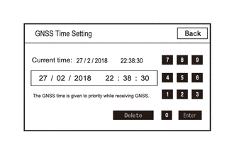
GNSS Time Setting
- HINT:
- ·
When the time cannot be correctly set, TOYOTA Connect cannot be used. Therefore, when the TOYOTA Connect demo is performed, etc., at a location where GNSS radio waves cannot be received such as inside a building, set the GNSS time setting using this function.
·When GNSS radio waves can be received, GNSS time is prioritized.
CHECK VEHICLE SIGNAL
- HINT:
-
For enter diagnostic mode and screen transition, refer toAudio / Visual / Telematics>AUDIO / VIDEO>AUDIO AND VISUAL SYSTEM (for 10.25 Inch Display)>DIAGNOSIS SYSTEM202304,999999,_56,_080751,_0599626,RM100000002B8WL,
Enter diagnostic mode.
Enter diagnostic mode.
Select "Function Check/Setting" from the "Service Menu" screen.
Select "Vehicle Signal" on the "Function Check/Setting I" screen to display the Vehicle Signal Check Mode screen.
Vehicle Signal Check Mode
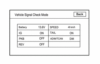
Check the vehicle signal status stored in the radio and display receiver assembly.
| Display | Content | Signal Input Terminal |
|---|---|---|
| Battery | Auxiliary battery voltage is displayed. | Terminal +B1 of the radio and display receiver assembly |
| IG | Ignition switch ON/OFF state is displayed. | Terminal IG of the radio and display receiver assembly |
| PKB | Parking brake ON/OFF state is displayed. | Terminal PKB of the radio and display receiver assembly |
| REV | Reverse signal ON/OFF state is displayed. | Terminal REV of the radio and display receiver assembly |
| SPEED | Vehicle speed is displayed in km/h. | Terminal SPD of the radio and display receiver assembly |
| TAIL | Tail signal (light control switch) ON/OFF state is displayed. | Terminal ILL+ of the radio and display receiver assembly |
| ADIM/TCAN | Brightness state DIM (with) / BRIGHT (without) is displayed. | Input via CAN communication |
- HINT:
- ·
This screen is updated once per second.
·If vehicle signals other than ADIM/TCAN is abnormal, inspect each terminal and wire harness.
·If vehicle signal ADIM/TCAN is abnormal, it can be judged that the CAN communication system is malfunctioning.
for HV Model: Click herePower Source / Network>NETWORKING>CAN COMMUNICATION SYSTEM (for HV Model)>HOW TO PROCEED WITH TROUBLESHOOTING202304,999999,_57,_080743,_0392424,RM100000002BB1R,
for Gasoline Model: Click herePower Source / Network>NETWORKING>CAN COMMUNICATION SYSTEM (for Gasoline Model (except NR Series))>HOW TO PROCEED WITH TROUBLESHOOTING202304,999999,_57,_080743,_0598531,RM100000002BFV9,
CHECK "Bluetooth" COMMUNICATION TRACE OUTPUT
- HINT:
-
For enter diagnostic mode and screen transition, refer toAudio / Visual / Telematics>AUDIO / VIDEO>AUDIO AND VISUAL SYSTEM (for 10.25 Inch Display)>DIAGNOSIS SYSTEM202304,999999,_56,_080751,_0599626,RM100000002B8WL,
Connect the USB memory device to the No. 1 stereo jack adapter assembly.
Enter diagnostic mode.
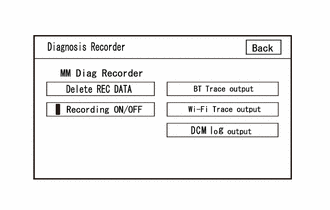
| *a | Green Indicator |
Start diagnosis and display the "Service Menu" screen.
Select "Failure Diagnosis" on the "Service Menu" screen to display the "Failure Diagnosis" screen.
Select "Diagnosis Recorder" on the "Failure Diagnosis" screen to display the "Diagnosis Recorder" screen.
Select "Recording ON/OFF" on the "Diagnosis Recorder" screen to turn off the indicator (green).
Press and hold (for 3 seconds) "BT Trace output" on the "Diagnosis Recorder" screen.
- HINT:
-
When the indicator (green) of "Recording ON/OFF" is illuminated, "BT Trace output" is grayed out and cannot be selected.
BT Trace Output
In accordance with the display, save the "Bluetooth" Connection History recorded data.
Select "Recording ON/OFF" on the "Diagnosis Recorder" screen to turn on the indicator (green).
- HINT:
- ·
When performing the above procedure, make sure to set the indicator (green) of "Recording ON/OFF" back to the illuminated state.
·The Bluetooth Connection History is stored in the ECU internal memory, and consists of timestamped operation data. By checking "Bluetooth" Connection History, the date, cause, etc. of a "Bluetooth" device failing to register or connect can be analyzed.
CHECK "Wi-Fi" COMMUNICATION TRACE OUTPUT
- HINT:
-
For enter diagnostic mode and screen transition, refer toAudio / Visual / Telematics>AUDIO / VIDEO>AUDIO AND VISUAL SYSTEM (for 10.25 Inch Display)>DIAGNOSIS SYSTEM202304,999999,_56,_080751,_0599626,RM100000002B8WL,
Connect the USB memory device to the No. 1 stereo jack adapter assembly.
Enter diagnostic mode.
| *a | Green Indicator |
Enter diagnostic mode.
Select "Failure Diagnosis" from the "Service Menu" screen.
Select "Diagnosis Recorder" from the "Failure Diagnosis" screen.
Select "Recording ON/OFF" on the "Diagnosis Recorder" screen and turn off the "Recording ON/OFF" green indicator.
Select "Wi-Fi Trace output" for 3 seconds.
- HINT:
-
When the green "Recording ON/OFF" indicator is illuminated, the "Wi-Fi" Trace output" is grayed out and cannot be selected.
"Wi-Fi" Trace Output
According to the instructions on the screen, save the "Wi-Fi" Connection History data to a USB memory device.
Select "Recording ON/OFF" on the Diagnosis Recorder screen to illuminate the green "Recording ON/OFF" indicator.
- HINT:
- ·
Make sure that the green "Recording ON/OFF" indicator returns to illuminated state, after performing the above procedure.
·This function is used to check the connection history when the connection between the radio and display receiver assembly and a "Wi-Fi" device is unstable.