METER / GAUGE / DISPLAY METER / GAUGE SYSTEM(for 12.3 Inch Display) Entire Combination Meter does not Operate
DESCRIPTION
This circuit is the power source circuit for the combination meter assembly. This circuit provides two types of power sources; one is a constant power source, and the other is an IG power source.
WIRING DIAGRAM
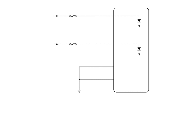
CAUTION / NOTICE / HINT
- NOTICE:
- ·
When replacing the combination meter assembly, always replace it with a new one. If a combination meter assembly which was installed to another vehicle is used, the information stored in it will not match the information from the vehicle and a DTC may be stored.
·When replacing the combination meter assembly, update the ECU security key.
·Inspect the fuses of circuits related to this system before performing the following procedure.
PROCEDURE
Disconnect the I4 combination meter assembly connector.
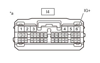
| *a | Front view of wire harness connector
(to Combination Meter Assembly) |
Measure the voltage according to the value(s) in the table below.
- Standard Voltage:
Tester Connection Condition Specified Condition I4-6 (IG+) - Body ground Ignition switch off Below 1 V I4-6 (IG+) - Body ground*1 Ignition switch ON 11 to 14 V I4-6 (IG+) - Body ground*2 Ignition switch ON 10.5 to 16 V
*1: for HV Model
*2: for Gasoline Model
- Result:
Proceed to OK NG
OK
NG
Disconnect the I4 combination meter assembly connector.
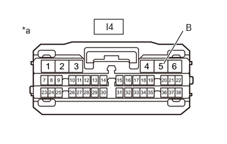
| *a | Front view of wire harness connector
(to Combination Meter Assembly) |
Measure the voltage according to the value(s) in the table below.
- Standard Voltage:
Tester Connection Condition Specified Condition I4-5 (B) - Body ground Always 11 to 14 V
- Result:
Proceed to OK NG
OK
NG
Measure the resistance according to the value(s) in the table below.
- Standard Resistance:
Tester Connection Condition Specified Condition I4-1 (EP) - Body ground Always Below 1 Ω I4-2 (ES) - Body ground Always Below 1 Ω
- Result:
Proceed to OK NG
OK
NG