PARKING BRAKE ELECTRIC PARKING BRAKE SYSTEM(for Gasoline Model) Electric Parking Brake System AUTO Function Circuit
DESCRIPTION
The skid control ECU (brake actuator assembly) receives shift position signals from the ECM via CAN communication to control the electric parking brake system AUTO function (shift-linked function).
The electric parking brake system AUTO function (shift-linked function) is automatically disabled when the ignition switch is ON, the brake pedal is depressed and the shift lever is moved out of P. Then, if the shift lever is moved to P, the AUTO function (shift-linked function) automatically operates to apply the electric parking brake.
WIRING DIAGRAM
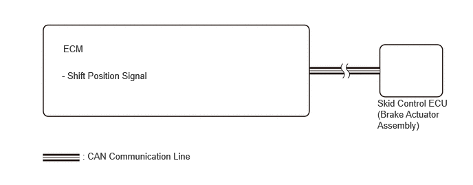
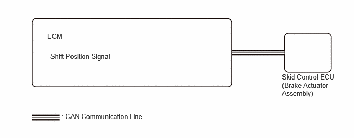
CAUTION / NOTICE / HINT
- NOTICE:
-
The AUTO function (shift-linked function) will not be automatically disabled when the ignition switch is ON, the brake pedal is depressed and the shift lever is moved out from P if the electric parking brake switch assembly is moved to the engage side. The AUTO function (shift-linked function) will not automatically operate to apply the electric parking brake when the shift lever is moved to P if the electric parking brake switch assembly is moved to the release side.
PROCEDURE
Check for DTCs.
- Powertrain > Engine > Trouble Codes
- 50001 372
- Result:
Result Proceed to DTC is not output A DTC is output B
A
B
for M15B-FKS: Click hereEngine / Hybrid System>M15B-FKS (ENGINE CONTROL)>SFI SYSTEM>HOW TO PROCEED WITH TROUBLESHOOTING202101,999999,_51,_096196,_0456237,RM100000001TN89,
for M15C-FKS: Click hereEngine / Hybrid System>M15C-FKS (ENGINE CONTROL)>SFI SYSTEM>HOW TO PROCEED WITH TROUBLESHOOTING202101,999999,_51,_096205,_0456238,RM100000001TNCS,
for M20A-FKS: Click hereEngine / Hybrid System>M20A-FKS (ENGINE CONTROL)>SFI SYSTEM>HOW TO PROCEED WITH TROUBLESHOOTING202104,999999,_51,_101144,_0469422,RM100000001VI4A,
for M20C-FKS: Click hereEngine / Hybrid System>M20C-FKS (ENGINE CONTROL)>SFI SYSTEM>HOW TO PROCEED WITH TROUBLESHOOTING202107,999999,_51,_105190,_0484152,RM100000001XA88,
for M20E-FKS: Click hereEngine / Hybrid System>M20E-FKS (ENGINE CONTROL)>SFI SYSTEM>HOW TO PROCEED WITH TROUBLESHOOTING202104,999999,_51,_101153,_0478272,RM100000001WJJL,
for NR Series: Click hereEngine / Hybrid System>NR Series (ENGINE CONTROL)>SFI SYSTEM>HOW TO PROCEED WITH TROUBLESHOOTING201906,999999,_51,_080777,_0393969,RM100000001I1R4,