RM3660EC _58 Vehicle Interior _080793 METER / GAUGE / DISPLAY _0598151 METER / GAUGE SYSTEM(except 12.3 Inch Display) J

METER / GAUGE / DISPLAY  METER / GAUGE SYSTEM(except 12.3 Inch Display)  Power Source Circuit  


WIRING DIAGRAM

except NR Series Engine
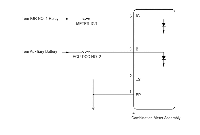

E492929E12
2.729,0.76 4.104,0.958 1.375,0.198 10 false METER-IGR 0.771,0.573 2.76,0.771 1.99,0.198 10 false from IGR NO. 1 Relay 2.604,1.938 4.438,2.135 1.833,0.198 10 false ECU-DCC NO. 2 0.771,1.75 2.458,2.021 1.688,0.271 10 false from Auxiliary Battery 4.865,0.479 5.323,0.677 0.458,0.198 10 false IG+ 4.865,1.667 5.021,1.865 0.156,0.198 10 false B 4.646,0.49 4.802,0.688 0.156,0.198 10 false 6 4.635,1.667 4.792,1.865 0.156,0.198 10 false 5 4.865,3.302 5.177,3.5 0.313,0.198 10 false EP 4.854,2.75 5.167,2.948 0.313,0.198 10 false ES 4.646,2.625 4.802,2.823 0.156,0.198 10 false 2 4.635,3.177 4.792,3.375 0.156,0.198 10 false 1 4.708,3.948 5.167,4.146 0.458,0.198 10 false I4 4.708,4.125 6.708,4.396 2,0.271 10 false Combination Meter Assembly


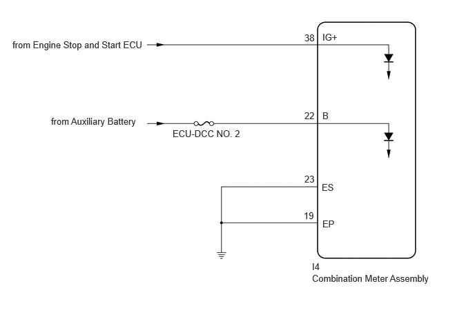
for NR Series Engine


E516200E02
0.188,0.594 2.177,0.792 1.99,0.198 10 false from Engine Stop and Start ECU 2.604,1.938 4.438,2.135 1.833,0.198 10 false ECU-DCC NO. 2 0.771,1.75 2.458,2.021 1.688,0.271 10 false from Auxiliary Battery 4.865,0.479 5.323,0.677 0.458,0.198 10 false IG+ 4.865,1.667 5.021,1.865 0.156,0.198 10 false B 4.594,0.49 4.917,0.844 0.323,0.354 10 false 38 4.594,1.667 5.073,2.156 0.479,0.49 10 false 22 4.865,3.302 5.177,3.5 0.313,0.198 10 false EP 4.854,2.75 5.167,2.948 0.313,0.198 10 false ES 4.594,2.625 4.948,2.958 0.354,0.333 10 false 23 4.583,3.177 5.01,3.615 0.427,0.438 10 false 19 4.708,3.948 5.167,4.146 0.458,0.198 10 false I4 4.708,4.125 6.708,4.396 2,0.271 10 false Combination Meter Assembly


CAUTION / NOTICE / HINT

NOTICE:
·

When replacing the combination meter assembly, always replace it with a new one. If a combination meter assembly which was installed to another vehicle is used, the information stored in it will not match the information from the vehicle and a DTC may be stored.

·

except NR Series Engine

When replacing the combination meter assembly, update the ECU security key.

Click hereGeneral>SETUP>WHEN REPLACING OR REMOVING/INSTALLING PARTS>UPDATE ECU SECURITY KEY

·

Inspect the fuses of circuits related to this system before performing the following procedure.


PROCEDURE

1.CONFIRM MODEL
a.

Choose the model to be inspected.


Result:
Result Proceed to
except NR Series Engine A
for NR Series Engine B


A

2.CHECK HARNESS AND CONNECTOR (IG POWER SOURCE CIRCUIT)

B

5.CHECK HARNESS AND CONNECTOR (IG POWER SOURCE CIRCUIT)
2.CHECK HARNESS AND CONNECTOR (IG POWER SOURCE CIRCUIT)
a.

Disconnect the I4 combination meter assembly connector.
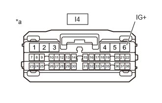

b.
E436104C40
1.427,0.292 1.865,0.521 0.438,0.229 2.688,0.958 2.865,0.458 true 2.885,0.281 3.198,0.479 0.313,0.198 10 false IG+ 1.583,0.323 1.896,0.521 0.313,0.198 10 false I4 0.333,0.375 0.646,0.573 0.313,0.198 10 false *a
*a Front view of wire harness connector
(to Combination Meter Assembly)


Measure the voltage according to the value(s) in the table below.

Standard Voltage:
Tester Connection Condition Specified Condition
I4-6 (IG+) - Body ground Ignition switch off Below 1 V
I4-6 (IG+) - Body ground*1 Ignition switch ON 11 to 14 V
I4-6 (IG+) - Body ground*2 Ignition switch ON 10.5 to 16 V


*1: for HV Model

*2: for Gasoline Model


Result:
Proceed to
OK
NG


OK

3.CHECK HARNESS AND CONNECTOR (+B POWER SOURCE CIRCUIT)

NG

REPAIR OR REPLACE HARNESS OR CONNECTOR

3.CHECK HARNESS AND CONNECTOR (+B POWER SOURCE CIRCUIT)
a.

Disconnect the I4 combination meter assembly connector.
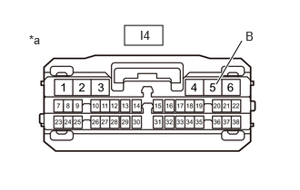

b.
E436104C41
1.427,0.292 1.865,0.521 0.438,0.229 2.479,0.969 2.771,0.469 true 2.813,0.333 3.125,0.531 0.313,0.198 10 false B 1.604,0.323 1.917,0.521 0.313,0.198 10 false I4 0.333,0.375 0.646,0.573 0.313,0.198 10 false *a
*a Front view of wire harness connector
(to Combination Meter Assembly)


Measure the voltage according to the value(s) in the table below.

Standard Voltage:
Tester Connection Condition Specified Condition
I4-5 (B) - Body ground Always 11 to 14 V


Result:
Proceed to
OK
NG


OK

4.CHECK HARNESS AND CONNECTOR (COMBINATION METER ASSEMBLY - BODY GROUND)

NG

REPAIR OR REPLACE HARNESS OR CONNECTOR

4.CHECK HARNESS AND CONNECTOR (COMBINATION METER ASSEMBLY - BODY GROUND)
a.

Measure the resistance according to the value(s) in the table below.

Standard Resistance:
Tester Connection Condition Specified Condition
I4-1 (EP) - Body ground Always Below 1 Ω
I4-2 (ES) - Body ground Always Below 1 Ω


Result:
Proceed to
OK
NG


OK

NG

REPAIR OR REPLACE HARNESS OR CONNECTOR

5.CHECK HARNESS AND CONNECTOR (IG POWER SOURCE CIRCUIT)
a.

Disconnect the I4 combination meter assembly connector.
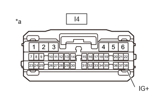

b.
E436104C76
1.427,0.292 1.865,0.521 0.438,0.229 2.896,1.865 2.708,1.469 true 2.979,1.813 3.292,2.01 0.313,0.198 10 false IG+ 1.594,0.323 1.906,0.521 0.313,0.198 10 false I4 0.333,0.375 0.646,0.573 0.313,0.198 10 false *a
*a Front view of wire harness connector
(to Combination Meter Assembly)


Measure the voltage according to the value(s) in the table below.

Standard Voltage:
Tester Connection Condition Specified Condition
I4-38 (IG+) - Body ground Ignition switch off Below 1 V
I4-38 (IG+) - Body ground Ignition switch ON 10.5 to 16 V


Result:
Proceed to
OK
NG


OK

6.CHECK HARNESS AND CONNECTOR (+B POWER SOURCE CIRCUIT)

NG

6.CHECK HARNESS AND CONNECTOR (+B POWER SOURCE CIRCUIT)
a.

Disconnect the I4 combination meter assembly connector.
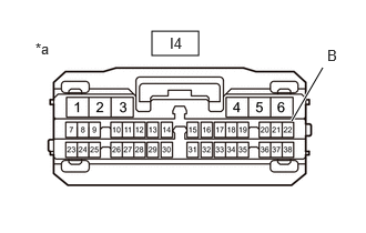

b.
E436104C77
1.427,0.292 1.865,0.521 0.438,0.229 2.74,1.135 3.031,0.635 true 3.073,0.438 3.385,0.635 0.313,0.198 10 false B 1.594,0.323 1.906,0.521 0.313,0.198 10 false I4 0.333,0.375 0.646,0.573 0.313,0.198 10 false *a
*a Front view of wire harness connector
(to Combination Meter Assembly)


Measure the voltage according to the value(s) in the table below.

Standard Voltage:
Tester Connection Condition Specified Condition
I4-22 (B) - Body ground Always 11 to 14 V


Result:
Proceed to
OK
NG


OK

7.CHECK HARNESS AND CONNECTOR (COMBINATION METER ASSEMBLY - BODY GROUND)

NG

REPAIR OR REPLACE HARNESS OR CONNECTOR

7.CHECK HARNESS AND CONNECTOR (COMBINATION METER ASSEMBLY - BODY GROUND)
a.

Measure the resistance according to the value(s) in the table below.

Standard Resistance:
Tester Connection Condition Specified Condition
I4-19 (EP) - Body ground Always Below 1 Ω
I4-23 (ES) - Body ground Always Below 1 Ω


Result:
Proceed to
OK
NG


OK

NG

REPAIR OR REPLACE HARNESS OR CONNECTOR