REAR SUSPENSION REAR AXLE BEAM INSTALLATION
PROCEDURE

 48727
1.INSTALL REAR SUSPENSION ARM BRACKET LH
48727
1.INSTALL REAR SUSPENSION ARM BRACKET LH
- HINT:
-
Perform this procedure only when replacement of the rear suspension arm bracket LH is necessary.
Install the rear suspension arm bracket LH to the vehicle body with the 4 bolts.
- Torque:
- 90 N*m (918 kgf*cm, 66 ft.*lbf)
Install the rear flexible hose LH to the rear suspension arm bracket LH with the bolt.
- Torque:
- 17 N*m (173 kgf*cm, 13 ft.*lbf)
Engage the hook and install the No. 2 parking brake wire assembly to the rear suspension arm bracket LH with the bolt.
- Torque:
- 8.0 N*m (82 kgf*cm, 71 in.*lbf)
- NOTICE:
-
Do not twist the skid control sensor wire when installing it.
48717
2.INSTALL REAR SUSPENSION ARM BRACKET RH
- HINT:
-
Perform this procedure only when replacement of the rear suspension arm bracket RH is necessary.
Install the rear suspension arm bracket RH to the vehicle body with the 4 bolts.
- Torque:
- 90 N*m (918 kgf*cm, 66 ft.*lbf)
Install the rear flexible hose RH to the rear suspension arm bracket RH with the bolt.
- Torque:
- 17 N*m (173 kgf*cm, 13 ft.*lbf)
Engage the hook and install the No. 2 parking brake wire assembly to the rear suspension arm bracket RH with the bolt.
- Torque:
- 8.0 N*m (82 kgf*cm, 71 in.*lbf)
- NOTICE:
-
Do not twist the skid control sensor wire when installing it.
Install the parking brake cable heat insulator to the rear suspension arm bracket RH with the 2 nuts.
- Torque:
- 8.0 N*m (82 kgf*cm, 71 in.*lbf)
3.TEMPORARILY INSTALL REAR AXLE BEAM ASSEMBLY
Slowly jack up the rear axle beam assembly with an engine lifter using 2 wooden blocks and 2 attachments or equivalent tools, and temporarily install the rear axle beam assembly to the rear suspension arm brackets LH and RH with the 2 bolts (B).
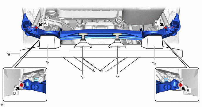
| *a | Engine Lifter | *b | Wooden Block |
| *c | Attachment | - | - |
- CAUTION:
-
Make sure to secure the rear axle beam assembly to prevent it from dropping.
Temporarily install the rear axle beam assembly to the rear shock absorber assemblies LH and RH with the 2 bolts (A).
48259A
4.INSTALL REAR UPPER COIL SPRING INSULATOR LH
48257C
5.INSTALL REAR UPPER COIL SPRING INSULATOR RH
- HINT:
-
Perform the same procedure as for the LH side.
48258C
6.INSTALL REAR LOWER COIL SPRING INSULATOR LH
48258B
7.INSTALL REAR LOWER COIL SPRING INSULATOR RH
- HINT:
-
Perform the same procedure as for the LH side.
8.INSTALL REAR COIL SPRING
42450B
9.INSTALL REAR AXLE HUB AND BEARING ASSEMBLY LH
42450A
10.INSTALL REAR AXLE HUB AND BEARING ASSEMBLY RH
- HINT:
-
Perform the same procedure as for the LH side.
47324
11.INSTALL REAR NO. 4 BRAKE TUBE
Install the rear No. 4 brake tube to the rear axle beam assembly.
47323
12.INSTALL REAR NO. 3 BRAKE TUBE
- HINT:
-
Perform the same procedure as for the rear No. 4 brake tube.
42431
13.INSTALL REAR DISC (for LH Side)
42431
14.INSTALL REAR DISC (for RH Side)
- HINT:
-
Perform the same procedure as for the LH side.
15.INSTALL REAR DISC BRAKE CALIPER ASSEMBLY LH
Install the rear disc brake caliper assembly LH with rear flexible hose LH with the 2 bolts.
- Torque:
- 107 N*m (1091 kgf*cm, 79 ft.*lbf)
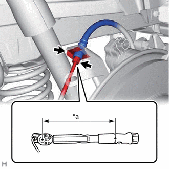
| *a | Torque Wrench Fulcrum Length |
Connect the rear No. 2 brake tube flexible hose to the rear axle beam assembly with a new clip.
- NOTICE:
-
Install the clip as far as it will go.
Using a union nut wrench, connect the rear No. 4 brake tube to the rear No. 2 brake tube flexible hose while holding the rear No. 2 brake tube flexible hose with a wrench.
- Torque:
- Specified tightening torque : 15.2 N*m (155 kgf*cm, 11 ft.*lbf)
- NOTICE:
- ·
Do not kink or damage the brake line.
·Do not allow any foreign matter such as dirt or dust to enter the brake line from the connecting parts.
- HINT:
- ·
Calculate the torque wrench reading when changing the fulcrum length of the torque wrench.
·When using a union nut wrench (fulcrum length of 22 mm (0.866 in.)) + torque wrench (fulcrum length of 162 mm (6.38 in.)):
13.4 N*m (137 kgf*cm, 10 ft.*lbf)
16.INSTALL REAR DISC BRAKE CALIPER ASSEMBLY RH
- HINT:
-
Perform the same procedure as for the LH side.
890C0A
17.INSTALL NO. 2 PARKING BRAKE WIRE ASSEMBLY
890C0
18.INSTALL NO. 1 PARKING BRAKE WIRE ASSEMBLY
- HINT:
-
Perform the same procedure as for the No. 2 parking brake wire assembly.
47319F
19.CONNECT REAR FLEXIBLE HOSE LH
47318F
20.CONNECT REAR FLEXIBLE HOSE RH
- HINT:
-
Perform the same procedure as for the LH side.
21.BLEED BRAKE LINE
22.INSTALL REAR WHEELS
23. STABILIZE SUSPENSION
42110F
24.FULLY TIGHTEN REAR AXLE BEAM ASSEMBLY
25.CHECK FOR SPEED SENSOR SIGNAL
26.INSPECT REAR WHEEL ALIGNMENT
27.PERFORM INITIALIZATION
| Parking Assist Monitor System | ( 202304,999999,_56,_080754,_0596561,RM100000002AX0C,) 202304,999999,_56,_080754,_0596561,RM100000002AX0C,)
|