THEFT DETERRENT / KEYLESS ENTRY IMMOBILISER SYSTEM(w/o Smart Entry and Start System) Key Cannot be Registered
DESCRIPTION
A maximum of 5 key ID codes can be registered.
WIRING DIAGRAM
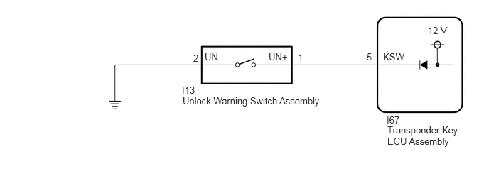
CAUTION / NOTICE / HINT
- NOTICE:
-
If the transponder key ECU assembly is replaced, refer to Service Bulletin.
PROCEDURE
Check that the system enters registration mode.
- OK:
System enters registration mode.
- Result:
Proceed to OK NG
OK
NG
In registration mode, insert the door control transmitter assembly into the ignition key cylinder and check the security indicator light (combination meter assembly).
- HINT:
-
If the new key ID code registration fails, code 2-1 will be output through the security light. Trying to re-register an already registered door control transmitter assembly will cause code 2-2 to be output when the door control transmitter assembly is inserted. If the number of registered key ID codes exceeds the maximum limit, code 2-3 will be output through the security indicator light (combination meter assembly). The output details are shown in the following illustration.
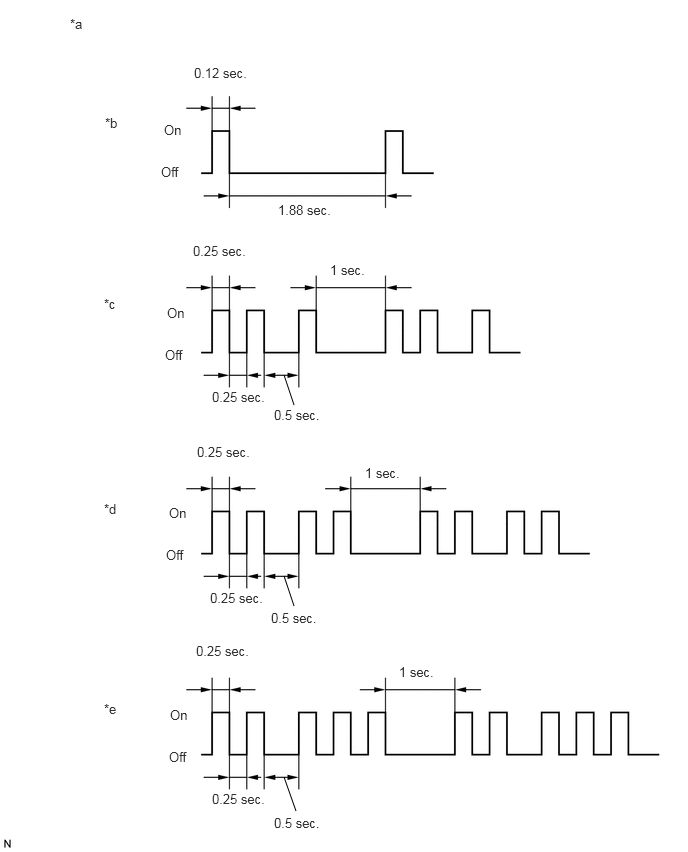
| *a | Security Indicator Light (Combination Meter Assembly) | *b | Normal (Immobiliser system is operating normally) |
| *c | Code 2-1 | *d | Code 2-2 |
| *e | Code 2-3 | - | - |
- Result:
Result Proceed to Code 2-1 or Code 2-3 is output A Code 2-2 is output B
A
B
Connect the GTS to the DLC3.
Turn the ignition switch to ON.
Turn the GTS on.
Enter the following menus: Body Electrical / Immobiliser / Data List.
Read the Data List according to the display on the GTS.
- Body Electrical > Immobiliser > Data List
-
Tester Display Measurement Item Range Normal Condition Diagnostic Note Transponder M-code Number of registered master key min. 0, max. 15 Number of registered master keys displayed -
- Body Electrical > Immobiliser > Data List
-
Tester Display Transponder M-code - 50003 260 19
- Result:
Result Proceed to 5 is displayed for "Transponder M-code" A Values are other than above B
A
B
Refer to the table below to determine if additional door control transmitter assemblies can be registered.
| Number of Door Control Transmitter Assemblies Registered | Proceed to |
|---|---|
| 0 | New key ID code registration |
| 1 to 5 | Additional key ID code registration |
Check if an additional door control transmitter assembly can be registered.
- OK:
Additional door control transmitter assembly can be registered.
- Result:
Proceed to OK NG
OK
NG
Remove the unlock warning switch assembly.
Inspect the unlock warning switch assembly.
- Result:
Proceed to OK NG
OK
NG
Disconnect the I67 transponder key ECU assembly connector.
Measure the resistance according to the value(s) in the table below.
- Standard Resistance:
Tester Connection Condition Specified Condition I13-1 (UN+) - I67-5 (KSW) Always Below 1 Ω I13-2 (UN-) - Body ground Always Below 1 Ω I13-1 (UN+) or I67-5 (KSW) - Other terminals and body ground Always 10 kΩ or higher
- Result:
Proceed to OK NG
OK
NG