THEFT DETERRENT / KEYLESS ENTRY IMMOBILISER SYSTEM(w/o Smart Entry and Start System) B2784 Antenna Coil Open / Short
DESCRIPTION
When an open or short circuit is detected in the antenna coil built into the transponder key coil, the transponder key ECU assembly stores this DTC.
| DTC No. | Detection Item | DTC Detection Condition | Trouble Area | Note |
|---|---|---|---|---|
| B2784 | Antenna Coil Open / Short | The antenna coil in the transponder key coil is open/shorted. | ·
Wire harness or connector ·
Transponder key coil ·
Transponder key ECU assembly |
DTC Output Confirmation Operation:
Insert the door control transmitter assembly into the ignition key cylinder. |
| Vehicle Condition when Malfunction Detected | Fail-safe Operation when Malfunction Detected |
|---|---|
| Engine cannot be started | - |
| DTC No. | Data List and Active Test |
|---|---|
| B2784 | Antenna Coil Status |
WIRING DIAGRAM
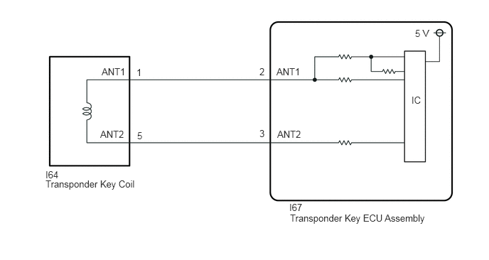
CAUTION / NOTICE / HINT
- NOTICE:
- ·
If the transponder key ECU assembly is replaced, refer to Service Bulletin.
·After repair, confirm that no DTCs are output by performing "DTC Output Confirmation Operation".
PROCEDURE
Check that the connector is properly connected to the transponder key coil.
- Result:
Proceed to NEXT
NEXT
Clear the DTCs.
- Body Electrical > Immobiliser > Clear DTCs
- 50002 260
- Result:
Proceed to NEXT
NEXT
Perform "DTC Output Confirmation Operation" procedure.
Check for DTCs.
- Body Electrical > Immobiliser > Trouble Codes
- 50001 260
- OK:
DTC B2784 is not output.
- Result:
Result Proceed to B2784 is not output A B2784 is output B
A
B
Disconnect the I64 transponder key coil connector.
Using an oscilloscope, check the waveform.
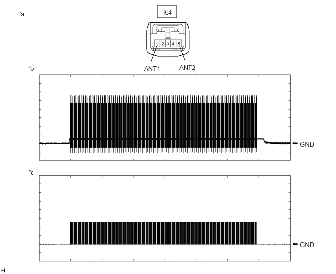
| *a | Front view of wire harness connector
(to Transponder Key Coil) |
*b | Waveform 1 |
| *c | Waveform 2 | - | - |
| Tester Connection | Condition | Tool Setting | Specified Condition |
|---|---|---|---|
| I64-1 (ANT1) - Body ground | Within 3 seconds of inserting door control transmitter assembly into ignition key cylinder | 20 V/DIV., 2 s./DIV. | Pulse generation
(See waveform 1) |
| I64-5 (ANT2) - Body ground | Within 3 seconds of inserting door control transmitter assembly into ignition key cylinder | 20 V/DIV., 2 s./DIV. | Pulse generation
(See waveform 2) |
- OK:
Waveform is similar to that shown in the illustration.
- Result:
Proceed to OK NG
OK
NG
Disconnect the I67 transponder key ECU assembly connector.
Measure the resistance according to the value(s) in the table below.
- Standard Resistance:
Tester Connection Condition Specified Condition I67-2 (ANT1) - I64-1 (ANT1) Always Below 1 Ω I67-3 (ANT2) - I64-5 (ANT2) Always Below 1 Ω I67-2 (ANT1) or I64-1 (ANT1) - Other terminals and body ground Always 10 kΩ or higher I67-3 (ANT2) or I64-5 (ANT2) - Other terminals and body ground Always 10 kΩ or higher
- Result:
Proceed to OK NG
OK
NG