SLIDING ROOF / CONVERTIBLE SLIDING ROOF HOUSING INSTALLATION
PROCEDURE

 63203F
1.INSTALL SLIDING ROOF HOUSING SUB-ASSEMBLY
63203F
1.INSTALL SLIDING ROOF HOUSING SUB-ASSEMBLY
- HINT:
-
As the illustration shown is an example, the actual details may differ.
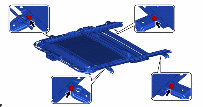
Loosen the 4 bolts of the brackets of the sliding roof or removable roof housing sub-assembly.
Temporarily install the sliding roof or removable roof housing sub-assembly with the 6 nuts and 8 bolts.
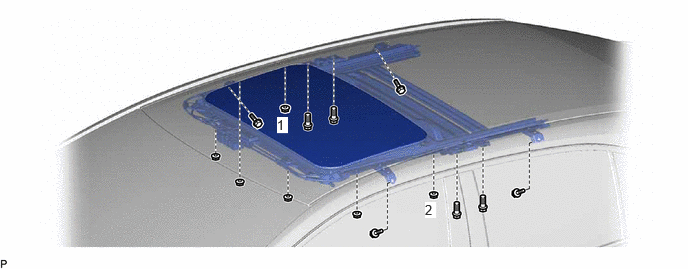
Tighten the 2 nuts.
- HINT:
-
Tighten the 2 nuts in the order shown in the illustration.
- Torque:
- 8.0 N*m (82 kgf*cm, 71 in.*lbf)
Tighten the 4 nuts.
- Torque:
- 8.0 N*m (82 kgf*cm, 71 in.*lbf)
for TFTM Made:
Tighten the 12 bolts to install the sliding roof or removable roof housing sub-assembly.
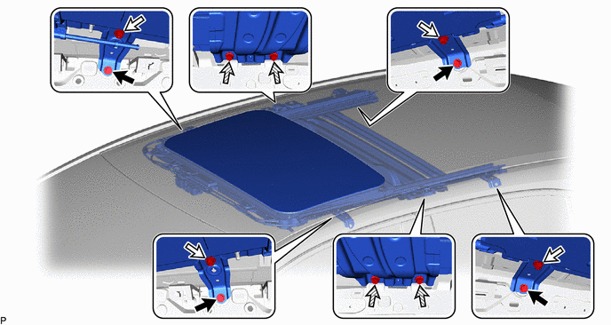

|
Bolt (A) | 
|
Bolt (B) |

|
Bolt (C) | - | - |
- HINT:
- ·
The brackets can be installed in any order.
·Tighten the bolts in the order of (A), (B) and then (C).
- Torque:
- Bolt (A), (C) : 8.0 N*m (82 kgf*cm, 71 in.*lbf)
- Bolt (B) : 5.4 N*m (55 kgf*cm, 48 in.*lbf)
for GTMC Made:
Tighten the 12 bolts to install the sliding roof or removable roof housing sub-assembly.
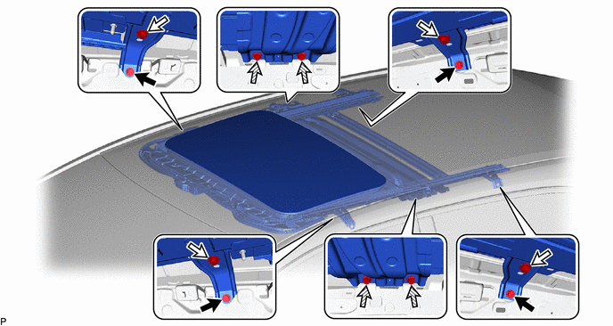
|
|
Bolt (A) |
|
Bolt (B) |
|
|
Bolt (C) | - | - |
- HINT:
- ·
The brackets can be installed in any order.
·Tighten the bolts in the order of (A), (B) and then (C).
- Torque:
- Bolt (A), (C) : 8.0 N*m (82 kgf*cm, 71 in.*lbf)
- Bolt (B) : 5.4 N*m (55 kgf*cm, 48 in.*lbf)
2.CONNECT SLIDING ROOF DRAIN HOSE
- HINT:
-
Use the same procedure for all of the sliding roof drain hoses.
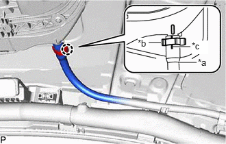
| *a | Drain Pipe |
| *b | Clamp |
| *c | Marking |
Connect the sliding roof drain hose.
- HINT:
-
Slide the hose to the base of the drain pipe.
Engage the claw to secure the sliding roof drain hose.
- HINT:
-
Make sure that the clamp is on the marking or between the marking and hose end.
63251H
3.INSTALL SLIDING ROOF WEATHERSTRIP
for TFTM Made:
Install the sliding roof weatherstrip.
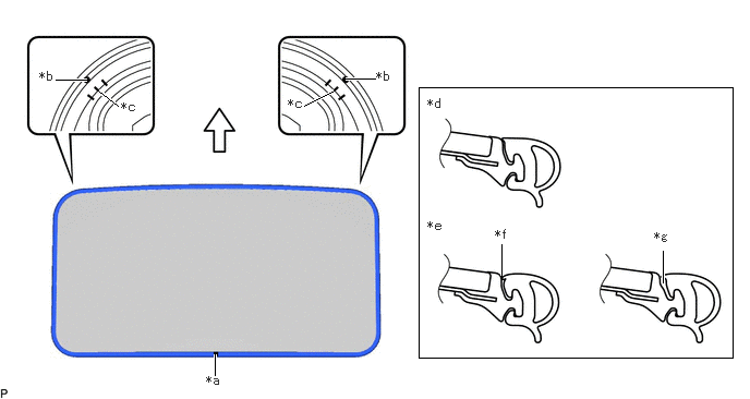
| *a | Joint | *b | Alignment Mark (Green) |
| *c | Middle Mark | *d | Correct |
| *e | Incorrect | *f | Pinched |
| *g | Gap (raised, wavy, etc.) | - | - |
|
|
Front Side | - | - |
Position the joint of the sliding roof weatherstrip on the rear side.
Align the alignment marks (green) on the sliding roof weatherstrip with the middle marks on the front corners of the sliding roof panel sub-assembly and install the sliding roof weatherstrip.
- HINT:
-
Make sure to install the lip of the sliding roof weatherstrip securely.
for GTMC Made Type A:
Install the sliding roof weatherstrip.
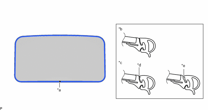
| *a | Joint | *b | Correct |
| *c | Incorrect | *d | Pinched |
| *e | Gap (raised, wavy, etc.) | - | - |
|
|
Front Side | - | - |
Position the joint of the sliding roof weatherstrip on the rear side.
Install the sliding roof weatherstrip.
- HINT:
-
Make sure to install the lip of the sliding roof weatherstrip securely.
for GTMC Made Type B:
Install the sliding roof weatherstrip.
| *a | Joint | *b | Alignment Mark (Green) |
| *c | Middle Mark | *d | Correct |
| *e | Incorrect | *f | Pinched |
| *g | Gap (raised, wavy, etc.) | - | - |
|
|
Front Side | - | - |
Position the joint of the sliding roof weatherstrip on the rear side.
Align the alignment marks (green) on the sliding roof weatherstrip with the middle marks on the front corners of the sliding roof panel sub-assembly and install the sliding roof weatherstrip.
- HINT:
-
Make sure to install the lip of the sliding roof weatherstrip securely.
63201G
4.INSTALL SLIDING ROOF GLASS SUB-ASSEMBLY
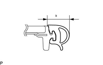
Measure the width (a) of the sliding roof weatherstrip.
- HINT:
-
This measurement will be used in a later step.
Using a T25 "TORX" socket wrench, temporarily install the sliding roof glass sub-assembly with the 4 screws.
Perform a level check.
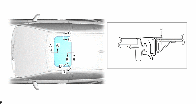
Check the difference in level "a" between the roof panel and the upper surface of the sliding roof weatherstrip when the sliding roof glass sub-assembly is fully closed.
- HINT:
-
"+" represents the condition that the glass is above the panel level. "-" represents the condition that the glass is below the panel level.
- Standard:
Area Measurement Area Measurement A - A -2.0 to 1.0 mm (-0.0787 to 0.0394 in.) B - B -1.0 to 2.0 mm (-0.0394 to 0.0787 in.) C - C -1.5 to 1.5 mm (-0.0591 to 0.0591 in.) D - D -1.0 to 1.5 mm (-0.0394 to 0.0591 in.)
Check the deformation of the sliding roof weatherstrip.
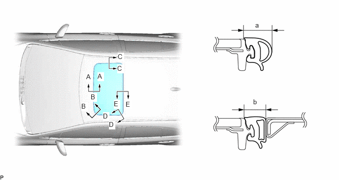
With the sliding roof glass sub-assembly in the fully closed position, measure the width (b) of the sliding roof weatherstrip and, using the width (a) measured in step a., calculate the deformation of the sliding roof weatherstrip (a - b).
- Standard:
Area Measurement Area Measurement A - A 0.5 to 2.5 mm (0.0197 to 0.0984 in.) B - B 0.8 to 2.8 mm (0.0315 to 0.1102 in.) C - C 0.5 to 2.5 mm (0.0197 to 0.0984 in.) D - D 0.8 to 2.8 mm (0.0315 to 0.1102 in.) E - E 0.5 to 2.5 mm (0.0197 to 0.0984 in.) - -
After adjusting the sliding roof glass sub-assembly, using a T25 "TORX" socket wrench, install the sliding roof glass sub-assembly with the 4 screws.
- Torque:
- 4.0 N*m (41 kgf*cm, 35 in.*lbf)
5.CHECK FOR WATER LEAK
After adjusting the sliding roof glass sub-assembly, check for water leakage into the vehicle interior.
If there are any leaks, readjust the sliding roof glass sub-assembly.
62180A
6.INSTALL CURTAIN SHIELD AIRBAG ASSEMBLY LH
62170A
7.INSTALL CURTAIN SHIELD AIRBAG ASSEMBLY RH
- HINT:
-
Use the same procedure as for the LH side.
63218G
8.INSTALL SLIDING ROOF SIDE GARNISH LH
Engage the 4 claws to install a new sliding roof side garnish LH.
63217G
9.INSTALL SLIDING ROOF SIDE GARNISH RH
- HINT:
-
Use the same procedure as for the LH side.
10.INITIALIZE SLIDING ROOF SYSTEM
for NR Series Engine: Click hereVehicle Exterior>SLIDING ROOF / CONVERTIBLE>SLIDING ROOF SYSTEM (for NR Series Engine)>INITIALIZATION202304,999999,_59,_080734,_0600093,RM100000002BB5I,
except NR Series Engine: Click hereVehicle Exterior>SLIDING ROOF / CONVERTIBLE>SLIDING ROOF SYSTEM (except NR Series Engine)>INITIALIZATION202304,999999,_59,_080734,_0600094,RM100000002BB62,
11.CHECK SLIDING ROOF SYSTEM
for NR Series Engine: Click hereVehicle Exterior>SLIDING ROOF / CONVERTIBLE>SLIDING ROOF SYSTEM (for NR Series Engine)>OPERATION CHECK202304,999999,_59,_080734,_0600093,RM100000002BB5G,
except NR Series Engine: Click hereVehicle Exterior>SLIDING ROOF / CONVERTIBLE>SLIDING ROOF SYSTEM (except NR Series Engine)>OPERATION CHECK202304,999999,_59,_080734,_0600094,RM100000002BB60,