☰ Toyota Levin Turbo☰ فهرستAudio / Visual / Telematics › AUDIO / VIDEO › AUDIO AND VISUAL SYSTEM(for Gasoline Model with Radio and Display Type (except 10.25 Inch Display))
RM3660EC
_56
Audio / Visual / Telematics
_080751
AUDIO / VIDEO
_0392314
AUDIO AND VISUAL SYSTEM(for Gasoline Model with Radio and Display Type (except 10.25 Inch Display))
J
AUDIO / VIDEO AUDIO AND VISUAL SYSTEM(for Gasoline Model with Radio and Display Type (except 10.25 Inch Display)) Reverse Signal Circuit
DESCRIPTION
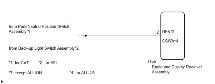
The radio and display receiver assembly receives a reverse signal from the park/neutral position switch assembly or back-up light switch assembly.
WIRING DIAGRAM
5.063,2.146 6.76,2.594
1.698,0.448
10
false
Radio and Display Receiver Assembly
4.938,1.958 5.333,2.156
0.396,0.198
10
false
I166
0.292,0.792 2.427,1.354
2.135,0.563
10
false
from Park/Neutral Position Switch Assembly*1
5.406,1.281 6.01,1.521
0.604,0.24
10
false
CSWA*4
5.219,0.99 5.375,1.188
0.156,0.198
10
false
2
0.302,1.521 2.854,2.083
2.552,0.563
10
false
from Back-up Light Switch Assembly*2
0.292,2.01 2.844,2.573
2.552,0.563
10
false
*1: for CVT
1.281,2 3.833,2.563
2.552,0.563
10
false
*2: for M/T
5.406,0.969 6.01,1.208
0.604,0.24
10
false
REV*3
0.281,2.344 2.813,2.667
2.531,0.323
10
false
*3: except ALLION
2.313,2.333 4.844,2.656
2.531,0.323
10
false
*4: for ALLION
PROCEDURE
1.CHECK MODEL
a.
Choose the model to be inspected.
- Result:
Result Proceed to except ALLION A for ALLION B
A
2.CHECK BACK-UP LIGHT
B
4.CHECK BACK-UP LIGHT
2.CHECK BACK-UP LIGHT
a.
Move the shift lever to R and check if the back-up lights come on.
- OK:
The back-up lights come on.
- Result:
Proceed to OK NG
OK
3.CHECK HARNESS AND CONNECTOR (REVERSE SIGNAL)
NG
3.CHECK HARNESS AND CONNECTOR (REVERSE SIGNAL)
a.
Disconnect the I166 radio and display receiver assembly connector.
b.
Measure the voltage according to the value(s) in the table below.
- Standard Voltage:
Tester Connection Condition Specified Condition I166-2 (REV) - Body ground Engine switch on (IG)
Shift lever in R11 to 14 V I166-2 (REV) - Body ground Engine switch on (IG)
Shift lever not in RBelow 1 V
- Result:
Proceed to OK NG
OK
PROCEED TO NEXT SUSPECTED AREA SHOWN IN PROBLEM SYMPTOMS TABLE
NG
REPAIR OR REPLACE HARNESS OR CONNECTOR
4.CHECK BACK-UP LIGHT
a.
Move the shift lever to R and check if the back-up lights come on.
- OK:
The back-up lights come on.
- Result:
Proceed to OK NG
OK
5.CHECK HARNESS AND CONNECTOR (REVERSE SIGNAL)
NG
5.CHECK HARNESS AND CONNECTOR (REVERSE SIGNAL)
a.
Disconnect the I166 radio and display receiver assembly connector.
b.
Measure the voltage according to the value(s) in the table below.
- Standard Voltage:
Tester Connection Condition Specified Condition I166-2 (CSWA) - Body ground Engine switch on (IG)
Shift lever in R11 to 14 V I166-2 (CSWA) - Body ground Engine switch on (IG)
Shift lever not in RBelow 1 V
- Result:
Proceed to OK NG
OK
PROCEED TO NEXT SUSPECTED AREA SHOWN IN PROBLEM SYMPTOMS TABLE
NG
REPAIR OR REPLACE HARNESS OR CONNECTOR