MAINTENANCE BRAKE VACUUM HOSE(for Gasoline Model) INSTALLATION
PROCEDURE

 44772
1.INSTALL CHECK VALVE TO CONNECTOR TUBE HOSE (for NR Series Engine)
44772
1.INSTALL CHECK VALVE TO CONNECTOR TUBE HOSE (for NR Series Engine)
Install the 2 clips to the check valve to connector tube hose.
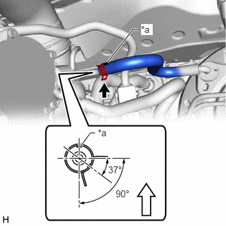
| *a | Paint Mark |

|
Up |
Connect the check valve to connector tube hose to the vacuum pump assembly and slide the clip to secure it.
- NOTICE:
- ·
When connecting the check valve to connector tube hose, face the paint mark up.
·Make sure that the tabs of the clip are aligned as shown in the illustration.
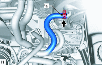
| *a | Paint Mark |
Connect the check valve to connector tube hose to the brake booster assembly and slide the clip to secure it.
- NOTICE:
- ·
When connecting the check valve to connector tube hose, face the paint mark up.
·Make sure that the tabs of the clip are facing upward.
44777
2.INSTALL NO. 1 VACUUM HOSE CONNECTOR (except NR Series Engine)
Align the No. 1 vacuum hose connector with the vacuum pump assembly, and push them together until the No. 1 vacuum hose connector makes a "click" sound.
- NOTICE:
- ·
Check that there is no foreign matter on the connecting parts.
·After connecting the No. 1 vacuum hose connector, check that the vacuum pump assembly and No. 1 vacuum hose connector are securely connected by pulling on them.
44772
3.INSTALL CHECK VALVE TO CONNECTOR TUBE HOSE (for M15A-FKS, M15B-FKS, M15C-FKS)
Install the 2 clips to the check valve to connector tube hose.
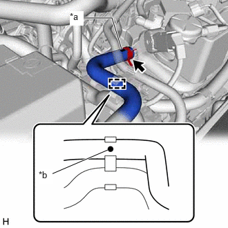
| *a | Paint Mark (A) |
| *b | Paint Mark (B) |
Connect the check valve to connector tube hose to the No. 1 vacuum hose connector and slide the clip to secure it.
- NOTICE:
- ·
When connecting the check valve to connector tube hose, face the paint mark (A) up.
·Make sure that the tabs of the clip are facing the rear of the vehicle.
Engage the clamp to install the check valve to connector tube hose.
- NOTICE:
-
Install the check valve to connector tube hose so that the paint mark (B) is positioned as shown in the illustration.
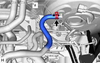
| *a | Paint Mark |
Connect the check valve to connector tube hose to the brake booster assembly and slide the clip to secure it.
- NOTICE:
- ·
When connecting the check valve to connector tube hose, face the paint mark up.
·Make sure that the tabs of the clip are facing upward.
44772
4.INSTALL CHECK VALVE TO CONNECTOR TUBE HOSE (for M20A-FKS, M20C-FKS, M20E-FKS)
Install the 2 clips to the check valve to connector tube hose.
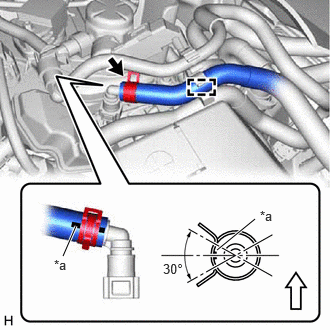
| *a | Paint Mark |
|
|
Up |
Connect the check valve to connector tube hose to the No. 1 vacuum hose connector and slide the clip to secure it.
- NOTICE:
- ·
When connecting the check valve to connector tube hose, make sure that the paint mark is facing the right side of the vehicle.
·Make sure that the tabs of the clip are aligned as shown in the illustration.
Engage the clamp to install the check valve to connector tube hose.
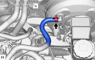
| *a | Paint Mark |
Connect the check valve to connector tube hose to the brake booster assembly and slide the clip to secure it.
- NOTICE:
- ·
When connecting the check valve to connector tube hose, face the paint mark up.
·Make sure that the tabs of the clip are facing upward.
55701J
5.INSTALL OUTER COWL TOP PANEL SUB-ASSEMBLY
55737B
6.INSTALL NO. 1 HEATER AIR DUCT SPLASH SHIELD SEAL (w/ No. 1 Heater Air Duct Splash Shield Seal)
7.INSTALL WINDSHIELD WIPER MOTOR AND LINK ASSEMBLY