NAVIGATION / MULTI INFO DISPLAY NAVIGATION SYSTEM(for Gasoline Model with RST Switch) Vehicle Speed Signal Circuit between Navigation Receiver Assembly and Combination Meter
DESCRIPTION
Vehicle speed signals are received from the combination meter assembly and used to cancel "Bluetooth" function operation.
The navigation receiver assembly recognizes that the vehicle is being driven and makes it impossible to connect or register a "Bluetooth" device while driving.
- HINT:
- ·
A voltage of 12 V or 5 V is output from each ECU and then input to the combination meter assembly. The signal is changed to a pulse signal at the transistor in the combination meter assembly. Each ECU controls its respective system based on this pulse signal.
·If a short occurs in any of the ECUs or in the wire harness connected to an ECU, all systems in the following diagram will not operate normally.
WIRING DIAGRAM
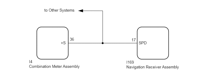
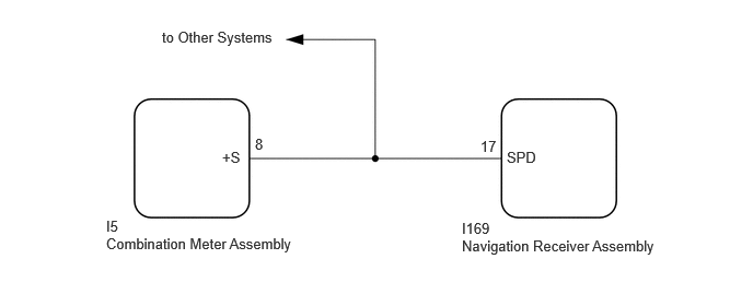
PROCEDURE
Choose the model to be inspected.
- Result:
Result Proceed to for Optitron Meter Type A for TFT Meter Type B
A
B
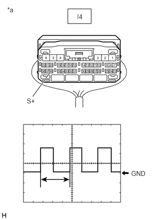
| *a | Component with harness connected
(Combination Meter Assembly) |
Check the output waveform.
Remove the combination meter assembly with the connector still connected.
Connect an oscilloscope to terminal I4-36 (+S) and body ground.
Turn the engine switch on (IG).
Turn a wheel slowly.
Check the signal waveform according to the condition(s) in the table below.
| Item | Condition |
|---|---|
| Measurement terminal | I4-36 (+S) - Body ground |
| Tool setting | 5 V/DIV., 20 ms./DIV. |
| Vehicle condition | Wheel being rotated |
- OK:
The waveform is similar to that shown in the illustration.
- HINT:
-
When the system is functioning normally, one wheel revolution generates 4 pulses. As the vehicle speed increases, the width indicated by (A) in the illustration narrows.
- Result:
Proceed to OK NG
OK
NG
Check the input waveform.
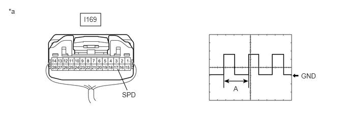
| *a | Component with harness connected
(Navigation Receiver Assembly) |
- | - |
Remove the navigation receiver assembly with the connector still connected.
Connect an oscilloscope to terminal I169-17 (SPD) and body ground.
Turn the engine switch on (IG).
Turn a wheel slowly.
Check the signal waveform according to the condition(s) in the table below.
| Item | Condition |
|---|---|
| Measurement terminal | I169-17 (SPD) - Body ground |
| Tool setting | 5 V/DIV., 20 ms./DIV. |
| Vehicle condition | Wheel being rotated |
- OK:
The waveform is similar to that shown in the illustration.
- HINT:
-
When the system is functioning normally, one wheel revolution generates 4 pulses. As the vehicle speed increases, the width indicated by (A) in the illustration narrows.
- Result:
Proceed to OK NG
OK
NG
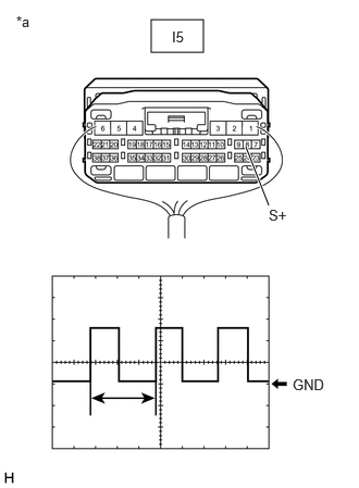
| *a | Component with harness connected
(Combination Meter Assembly) |
Check the output waveform.
Remove the combination meter assembly with the connector still connected.
Connect an oscilloscope to terminal I5-8 (+S) and body ground.
Turn the engine switch on (IG).
Turn a wheel slowly.
Check the signal waveform according to the condition(s) in the table below.
| Item | Condition |
|---|---|
| Measurement terminal | I5-8 (+S) - Body ground |
| Tool setting | 5 V/DIV., 20 ms./DIV. |
| Vehicle condition | Wheel being rotated |
- OK:
The waveform is similar to that shown in the illustration.
- HINT:
-
When the system is functioning normally, one wheel revolution generates 4 pulses. As the vehicle speed increases, the width indicated by (A) in the illustration narrows.
- Result:
Proceed to OK NG
OK
NG
Check the input waveform.
| *a | Component with harness connected
(Navigation Receiver Assembly) |
- | - |
Remove the navigation receiver assembly with the connector still connected.
Connect an oscilloscope to terminal I169-17 (SPD) and body ground.
Turn the engine switch on (IG).
Turn a wheel slowly.
Check the signal waveform according to the condition(s) in the table below.
| Item | Condition |
|---|---|
| Measurement terminal | I169-17 (SPD) - Body ground |
| Tool setting | 5 V/DIV., 20 ms./DIV. |
| Vehicle condition | Wheel being rotated |
- OK:
The waveform is similar to that shown in the illustration.
- HINT:
-
When the system is functioning normally, one wheel revolution generates 4 pulses. As the vehicle speed increases, the width indicated by (A) in the illustration narrows.
- Result:
Proceed to OK NG
OK
NG