PARK ASSIST / MONITORING TOYOTA PARKING ASSIST-SENSOR SYSTEM(w/ Parking Support Brake System) C1AE487 Ultrasonic Sensor (Front Right Corner) Missing Message
DESCRIPTION
This DTC is stored when an open circuit or short occurs in the communication line between the front corner ultrasonic sensor RH and the clearance warning ECU, or when a malfunction occurs in the front corner ultrasonic sensor RH.
| DTC No. | Detection Item | DTC Detection Condition | Trouble Area |
|---|---|---|---|
| C1AE487 | Ultrasonic Sensor (Front Right Corner) Missing Message | Front corner ultrasonic sensor RH lost communication | ·
Front corner ultrasonic sensor RH ·
Harness or connector ·
Clearance warning ECU assembly |
WIRING DIAGRAM
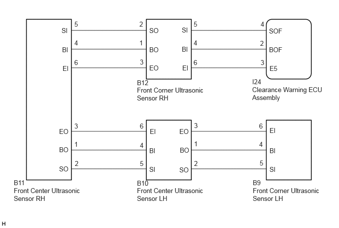
CAUTION / NOTICE / HINT
- NOTICE:
- ·
Perform registration after replacing or removing and installing the ultrasonic sensor or clearance warning ECU assembly.
·If a DTC is detected again after the repair, turn the ignition switch to ON and turn the TOYOTA parking assist-sensor system on, and then clear the DTC.
PROCEDURE
Check the vehicle condition and work details.
- Result:
Result Proceed to The clearance warning ECU assembly or ultrasonic sensor has not been replaced A The clearance warning ECU assembly or ultrasonic sensor has been replaced B
A
B
Check that the connector is properly connected to the front corner ultrasonic sensor and front center ultrasonic sensor.
- Result:
Proceed to NEXT
NEXT
According to the display on the GTS, check for DTCs.
- Body Electrical > Clearance Warning > Trouble Codes
- 50001 438
According to the display on the GTS, clear the DTCs.
- Body Electrical > Clearance Warning > Clear DTCs
- 50002 438
Recheck for DTCs.
- Body Electrical > Clearance Warning > Trouble Codes
- 50001 438
- Result:
Result Proceed to C1AE487 is not output A C1AE487 is output B
A
B
Check that the connector is properly connected to the clearance warning ECU assembly.
- Result:
Proceed to NEXT
NEXT
According to the display on the GTS, check for DTCs.
- Body Electrical > Clearance Warning > Trouble Codes
- 50001 438
According to the display on the GTS, clear the DTCs.
- Body Electrical > Clearance Warning > Clear DTCs
- 50002 438
Recheck for DTCs.
- Body Electrical > Clearance Warning > Trouble Codes
- 50001 438
| Symptoms | DTC Detection | |||
|---|---|---|---|---|
| C1AE487 | C1AE387 | C1AE287 | C1AE187 | |
| Symptom 1 | Not output | Not output | Not output | Not output |
| Symptom 2 | Output | Output | Output | Output |
| Symptom 3 | Not output | Output | Output | Output |
| Symptom 4 | Not output | Not output | Output | Output |
| Symptom 5 | Not output | Not output | Not output | Output |
| Symptom 6 | Output | Not output | Not output | Not output |
- Result:
Result Proceed to Listed under symptom 1 in combination table A Listed under symptom 2 in combination table B Listed under symptom 3 in combination table C Listed under symptom 4 in combination table D Listed under symptom 5 in combination table E Listed under symptom 6 in combination table F
A
B
C
D
E
F
Disconnect the I24 clearance warning ECU connector.
Disconnect the B12 front corner ultrasonic sensor RH connector.
Measure the resistance according to the value(s) in the table below.
- Standard Resistance:
Tester Connection Condition Specified Condition I24-2 (BOF) - B12-4 (BI) Always Below 1 Ω I24-4 (SOF) - B12-5 (SI) Always Below 1 Ω I24-3 (E5) - B12-6 (EI) Always Below 1 Ω I24-2 (BOF) or B12-4 (BI) - Body ground Always 10 kΩ or higher I24-4 (SOF) or B12-5 (SI) - Body ground Always 10 kΩ or higher I24-3 (E5) or B12-6 (EI) - Body ground Always 10 kΩ or higher
- Result:
Proceed to OK NG
OK
NG
Replace the front corner ultrasonic sensor RH with a new or normally functioning one.
- HINT:
-
To check if the ultrasonic sensor is functioning correctly, replace it with another ultrasonic sensor.
- Result:
Proceed to NEXT
NEXT
According to the display on the GTS, check for DTCs.
- Body Electrical > Clearance Warning > Trouble Codes
- 50001 438
According to the display on the GTS, clear the DTCs.
- Body Electrical > Clearance Warning > Clear DTCs
- 50002 438
Recheck for DTCs.
- Body Electrical > Clearance Warning > Trouble Codes
- 50001 438
- Result:
Result Proceed to No DTC is output A "C1AE487" is output B
A
B