AUDIO / VIDEO AUDIO AND VISUAL SYSTEM(for Gasoline Model with Radio and Display Type (except 10.25 Inch Display)) Radio Broadcast cannot be Received or Poor Reception
PROCEDURE
Check the radio automatic station search function.
Check the radio automatic station search function by activating it.
- Result:
Result Proceed to Automatic station search function does not stop. A Automatic station search function stops on a station. B
A
B
Check if any optional components that may decrease reception capacity, such as a sunshade film or telephone antenna, are installed.
- Result:
Result Proceed to Optional components are not installed. A Optional components are installed. B
- NOTICE:
-
Do not remove optional components without the permission of the customer.
A
B
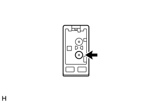
Preparation for check
Disconnect the antenna connector from the radio and display receiver assembly.
Check for noise
Turn the engine switch on (ACC) with the radio and display receiver assembly connector connected.
Turn the radio on and tune into FM mode.
Place a screwdriver, thin wire or other metal object on the radio and display receiver assembly antenna jack and check that noise can be heard from the speakers.
- OK:
Noise can be heard from the speakers.
- Result:
Proceed to OK NG
OK
NG
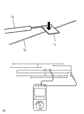
| *a | Tester Probe |
| *b | Antenna Wire |
| *c | Tin Foil |
Check for continuity in the window glass antenna wire.
- NOTICE:
-
When cleaning the glass, wipe it in the direction of the wire with a soft dry cloth. Take care not to damage the wire. Do not use detergents or glass cleaners with abrasive ingredients. When measuring resistance, wrap a piece of tin foil around the tip of each probe and press the foil against the wire with your finger, as shown in the illustration.
- HINT:
-
Check for continuity at the center of each antenna wire as shown in the illustration.
- OK:
There is continuity in the window glass antenna wire.
- Result:
Proceed to OK NG
OK
NG
Disconnect the RA radio and display receiver assembly connector.
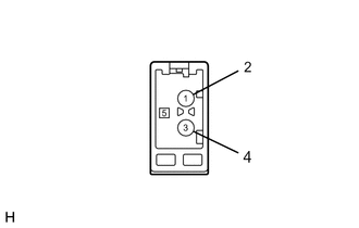
| *a | Component without harness connected
(Radio and Display Receiver Assembly) |
Measure the voltage according to the value(s) in the table below.
- Standard Voltage:
Tester Connection Condition Specified Condition RA-5 (ANT+) - Body ground Engine switch on (ACC)
Radio switch on and FM selected11 to 14 V
- Result:
Proceed to OK NG
OK
NG
Replace the antenna cord sub-assembly with a new or known good one and check if radio broadcasts can be received normally.
- OK:
Radio broadcasts can be received normally.
- Result:
Proceed to OK NG
OK
NG
Replace the No. 2 antenna cord sub-assembly with a new or known good one and check if radio broadcasts can be received normally.
- OK:
Radio broadcasts can be received normally.
- Result:
Proceed to OK NG
OK
NG
Replace the No. 1 amplifier antenna assembly with a new or known good one and check if radio broadcasts can be received normally.
- OK:
Radio broadcasts can be received normally.
- Result:
Proceed to OK NG
OK
NG
Replace the No. 3 antenna cord sub-assembly with a new or known good one and check if radio broadcasts can be received normally.
- OK:
Radio broadcasts can be received normally.
- Result:
Proceed to OK NG
OK
NG