NR Series ENGINE CONTROL SFI SYSTEM P045500 Evaporative Emission System Leak Detected (Large Leak) P045600 Evaporative Emission System Leak Detected (Very Small Leak)
DTC SUMMARY
| DTC No. | Detection Item | DTC Detection Condition | Trouble Area | MIL | Memory | Note |
|---|---|---|---|---|---|---|
| P045500 | Evaporative Emission System Leak Detected (Large Leak) | Leak detection pump creates negative pressure (vacuum) in EVAP system and EVAP system pressure is measured. Reference pressure is measured at start and end of leak check.
If stabilized pressure is higher than [second reference pressure x 0.2], ECM determines that EVAP system has a large leak. |
·
Fuel cap (loose) ·
Leakage from EVAP line (canister - fuel tank) ·
Leakage from EVAP line (purge VSV - canister) ·
Leakage from canister pump module ·
Leakage from fuel tank ·
Leakage from canister |
Comes on | DTC stored | SAE Code: P0455 |
| P045600 | Evaporative Emission System Leak Detected (Very Small Leak) | Leak detection pump creates negative pressure (vacuum) in EVAP system and EVAP system pressure is measured. Reference pressure measured at start and end of leak check.
If stabilized pressure is higher than second reference pressure, ECM determines that EVAP system has a small leak. |
·
Fuel cap (loose) ·
Leakage from EVAP line (canister - fuel tank) ·
Leakage from EVAP line (purge VSV - canister) ·
Leakage from canister pump module ·
Leakage from fuel tank ·
Leakage from canister |
Comes on | DTC stored | SAE Code: P0456 |
| DTC No. | Monitoring Item | Detection Timing | Detection Logic | SAE |
|---|---|---|---|---|
| P045500 | EVAP gross leak | While ignition switch off | 2 trip | P0455 |
| P045600 | EVAP small leak | While ignition switch off | 2 trip | P0456 |
DESCRIPTION
The description can be found in EVAP (Evaporative Emission) System.
MONITOR DESCRIPTION
5 hours*1 after the ignition switch is turned off, the leak detection pump creates negative pressure (vacuum) in the EVAP (Evaporative Emission) system. The ECM monitors for leaks and actuator malfunctions based on the EVAP pressure.
- HINT:
-
*: If the engine coolant temperature is not below 35°C (95°F) 5 hours after the ignition switch is turned off, the monitor check starts 2 hours later. If it is still not below 35°C (95°F) 7 hours after the ignition switch is turned off, the monitor check starts 2.5 hours later.
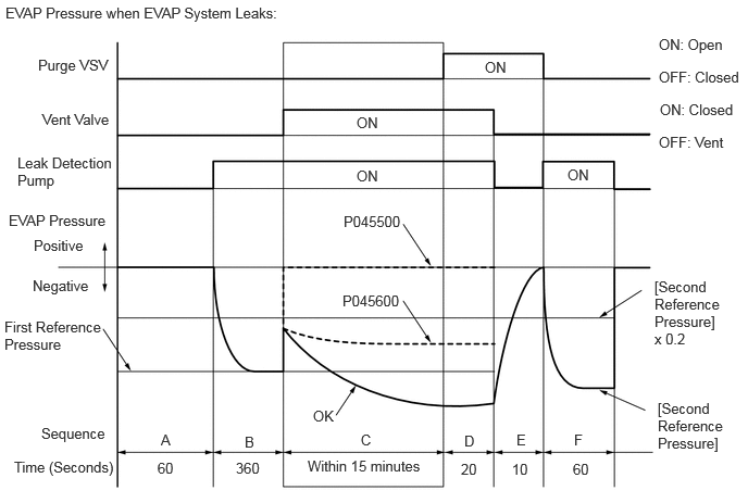
| Sequence | Operation | Description | Duration |
|---|---|---|---|
| - | ECM activation | Activated by soak timer 5, 7 or 9.5 hours after ignition switch turned off. | - |
| A | Atmospheric pressure measurement | Vent valve is turned off (vent) and EVAP system pressure is measured by ECM in order to register atmospheric pressure.
If pressure in EVAP system is not between 70 kPa(abs) and 110 kPa(abs) [10.15 psi(abs) and 15.95 psi(abs)], ECM cancels EVAP system monitor. |
60 seconds |
| B | First reference pressure measurement | In order to determine reference pressure, leak detection pump creates negative pressure (vacuum) through reference orifice and then ECM checks if leak detection pump and vent valve operate normally. | 360 seconds |
| C | EVAP system pressure measurement | Vent valve is turned on (closed) to shut EVAP system.
Negative pressure (vacuum) is created in EVAP system, and EVAP system pressure is then measured. Write down measured value as it will be used in leak check. If EVAP pressure does not stabilize within 15 minutes, ECM cancels EVAP system monitor. |
15 minutes* |
| D | No. 1 Check Valve monitor | Purge VSV is opened and then EVAP system pressure is measured by ECM.
If the pressure does not change, ECM interprets this as normal. |
20 seconds |
| E | Vent Valve monitor | Vent valve is turned off (vent) and then EVAP system pressure is measured by ECM.
Large increase indicates normal. |
10 seconds |
| F | Second reference pressure measurement | After second reference pressure measurement, leak check is performed by comparing first and second reference pressure measurements.
If stabilized system pressure is higher than second reference pressure, ECM determines that EVAP system is leaking. |
60 seconds |
| - | Final check | Atmospheric pressure is measured and then monitoring result is recorded by ECM. | - |
*: If only a small amount of fuel is in the fuel tank, it takes longer for the EVAP pressure to stabilize.
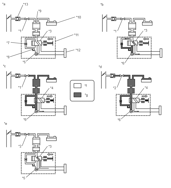
| *1 | Purge VSV: Off (Closed) | *2 | Purge VSV: On (Open) |
| *3 | Vent Valve: Off (Vent) | *4 | Vent Valve: On (Closed) |
| *5 | Leak Detection Pump: Off | *6 | Leak Detection Pump: On |
| *7 | Reference Orifice (0.02 inch) | *8 | Canister Pressure Sensor |
| *9 | Canister | *10 | Fuel Tank |
| *11 | Canister Pump Module | *12 | Canister Filter |
| *13 | No. 1 Check Valve | - | - |
| *a | Operation A:
Atmospheric Pressure Measurement |
*b | Operation B, F:
Reference Pressure Measurement |
| *c | Operation C:
EVAP System Pressure Measurement |
*d | Operation D:
No. 1 Check Valve Monitor |
| *e | Operation E:
Vent Valve Monitor |
*f | Atmospheric Pressure |
| *g | Negative Pressure | - | - |
(a) P045500: EVAP (Evaporative Emission) gross leak
In operation C, the leak detection pump creates negative pressure (vacuum) in the EVAP system and the EVAP system pressure is measured. If the stabilized system pressure is higher than [second reference pressure x 0.2] (near atmospheric pressure), the ECM determines that the EVAP system has a large leak, illuminates the MIL and stores the DTC (2 trip detection logic).
(b) P045600: EVAP very small leak
In operation C, the leak detection pump creates negative pressure (vacuum) in the EVAP system and the EVAP system pressure is measured. If the stabilized system pressure is higher than second reference pressure, the ECM determines that the EVAP system has a small leak, illuminates the MIL and stores the DTC (2 trip detection logic).
MONITOR STRATEGY
| Required Sensors/Components | Purge VSV
Canister pump module |
| Frequency of Operation | Once per driving cycle |
CONFIRMATION DRIVING PATTERN
- NOTICE:
- ·
The Evaporative System Check (Automatic Mode) consists of 7 steps performed automatically by the GTS. It takes a maximum of approximately 24 minutes.
·Do not perform the Evaporative System Check when the fuel tank is higher than 90% full because the cut-off valve may be closed, making the fuel tank leak check unavailable.
·Do not run the engine during this operation.
·When the temperature of the fuel is 35°C (95°F) or higher, a large amount of vapor forms and any check results become inaccurate. When performing the Evaporative System Check, keep the fuel temperature below 35°C (95°F).
- HINT:
- ·
After repair has been completed, clear the DTC and then check that the vehicle has returned to normal by performing the following All Readiness check procedure.
·When clearing the permanent DTCs, refer to the "CLEAR PERMANENT DTC" procedure.
Connect the GTS to the DLC3.
Turn the ignition switch to ON.
Turn the GTS on.
Clear the DTCs (even if no DTCs are stored, perform the clear DTC procedure).
Turn the ignition switch off and wait for at least 30 seconds.
Turn the ignition switch to ON [A].
Turn the GTS on.
Enter the following menus: Powertrain / Engine / Utility / Evaporative System Check / Automatic Mode [B].
After the Evaporative System Check is completed, check for All Readiness by entering the following menus: Powertrain / Engine / Utility / All Readiness.
Input the DTC: P045500 or P045600.
Check the DTC judgment result.
| GTS Display | Description |
|---|---|
| NORMAL | ·
DTC judgment completed ·
System normal |
| ABNORMAL | ·
DTC judgment completed ·
System abnormal |
| INCOMPLETE | ·
DTC judgment not completed ·
Perform driving pattern after confirming DTC enabling conditions |
- HINT:
- ·
If the judgment result shows NORMAL, the system is normal.
·If the judgment result shows ABNORMAL, the system has a malfunction.
·[A] to [B]: Normal judgment procedure.
The normal judgment procedure is used to complete DTC judgment and also used when clearing permanent DTCs.
·When clearing the permanent DTCs, do not disconnect the cable from the battery terminal or attempt to clear the DTCs during this procedure, as doing so will clear the universal trip and normal judgment histories.
PROCEDURE
- Result:
Proceed to NEXT
NEXT