NR Series ENGINE CONTROL SFI SYSTEM Fuel Pump Control Circuit
DESCRIPTION
The fuel pump circuit consists of the ECM, fuel pump (for low pressure side) and fuel pump control ECU assembly (which operates the fuel pump). Based on the engine output, the ECM determines the fuel pump speed. The speed is then converted to a duty signal and sent to the fuel pump control ECU assembly. Based on the signal sent from the ECM, the fuel pump control ECU assembly adjust the fuel pump operation speed.
WIRING DIAGRAM
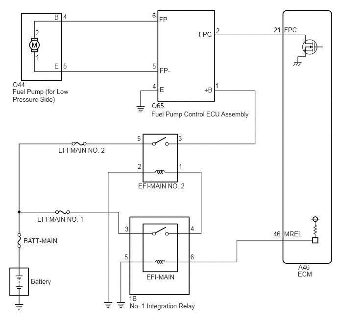
CAUTION / NOTICE / HINT
- NOTICE:
-
Inspect the fuses for circuits related to this system before performing the following procedure.
PROCEDURE
Connect the GTS to the DLC3.
Turn the ignition switch to ON.
Turn the GTS on.
Enter the following menus: Powertrain / Engine / Active Test / Activate the Circuit Relay.
- Powertrain > Engine > Active Test
-
Tester Display Activate the Circuit Relay - 50004 372 24
Check whether operating sounds can be heard while operating the fuel pump (for low pressure side) using the GTS.
- OK:
Operating sounds can be heard from the fuel pump (for low pressure side).
- Result:
Proceed to OK NG
OK
NG
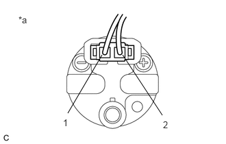
| *a | Component with harness connected
(Fuel Pump (for Low Pressure Side)) |
Remove the fuel pump (for low pressure side) from the fuel tank assembly.
Clean the fuel pump to completely remove any remaining fuel.
Connect the fuel pump connector.
- CAUTION:
-
Make sure that there is no fuel remaining inside or on the outside of the fuel pump.
Connect the GTS to the DLC3.
Turn the ignition switch to ON.
Turn the GTS on.
Enter the following menus: Powertrain / Engine / Active Test / Control the Fuel Pump Duty Ratio.
- Powertrain > Engine > Active Test
-
Tester Display Control the Fuel Pump Duty Ratio - 50004 372 10
Operate the fuel pump (for low pressure side) using the Active Test function and measure the voltage according to the value(s) in the table below.
- Standard Voltage:
Tester Connection GTS Operation Specified Condition 1 - 2 Fuel pump duty ratio: 25% 3.2 to 4.05 V Fuel pump duty ratio: 80% 8.8 to 12.5 V
Enter the following menus: Powertrain / Engine / Active Test / Activate the Circuit Relay.
- Powertrain > Engine > Active Test
-
Tester Display Activate the Circuit Relay - 50004 372 24
Operate the fuel pump (for low pressure side) using the Active Test function and measure the voltage according to the value(s) in the table below.
- Standard Voltage:
Tester Connection GTS Operation Specified Condition 1 - 2 ON (Fuel pump duty ratio: 90%) 9.0 to 14.0 V
- HINT:
- ·
Be sure to measure the voltage with all the connectors connected.
·Before performing this inspection, check that the battery voltage is between 11 and 14 V (not depleted).
- Result:
Proceed to OK NG
OK
NG
Inspect the fuel pump (for low pressure side).
- Result:
Proceed to OK NG
OK
NG
Disconnect the fuel pump control ECU assembly connector.
Disconnect the ECM connector.
Measure the resistance according to the value(s) in the table below.
- Standard Resistance:
Tester Connection Condition Specified Condition O65-2 (FPC) - A46-21 (FPC) Always Below 1 Ω O65-2 (FPC) or A46-21 (FPC) - Body ground and other terminals Always 10 kΩ or higher
- Result:
Proceed to OK NG
OK
NG
Replace the fuel pump (for low pressure side).
- HINT:
-
Perform "Inspection After Repair" after replacing the fuel pump (for low pressure side).
- Result:
Proceed to NEXT
NEXT
Check the fuel pump operation.
- OK:
Malfunction has been repaired successfully.
- Result:
Proceed to OK NG
OK
NG
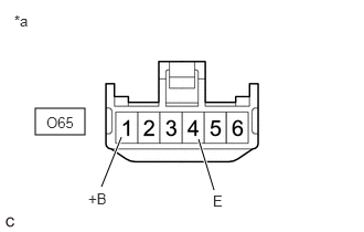
| *a | Front view of wire harness connector
(to Fuel Pump Control ECU Assembly) |
Disconnect the fuel pump control ECU assembly connector.
Turn the ignition switch to ON.
Measure the voltage according to the value(s) in the table below.
- Standard Voltage:
Tester Connection Condition Specified Condition O65-1 (+B) - O65-4 (E) Ignition switch ON 11 to 14 V
- Result:
Proceed to OK NG
OK
NG
Inspect the fuel pump (for low pressure side).
- HINT:
-
Perform "Inspection After Repair" after replacing the fuel pump (for low pressure side).
- Result:
Proceed to OK NG
OK
NG
Disconnect the fuel pump (for low pressure side) connector.
Disconnect the fuel pump control ECU assembly connector.
Measure the resistance according to the value(s) in the table below.
- Standard Resistance:
Tester Connection Condition Specified Condition O44-4 (B) - O65-6 (FP) Always Below 1 Ω O44-5 (E) - O65-5 (FP-) Always Below 1 Ω O44-4 (B) or O65-6 (FP) - Body ground and other terminals Always 10 kΩ or higher O44-5 (E) or O65-5 (FP-) - Body ground and other terminals Always 10 kΩ or higher
- Result:
Proceed to OK NG
OK
NG
Disconnect the fuel pump control ECU assembly connector.
Disconnect the ECM connector.
Measure the resistance according to the value(s) in the table below.
- Standard Resistance:
Tester Connection Condition Specified Condition O65-2 (FPC) - A46-21 (FPC) Always Below 1 Ω O65-2 (FPC) or A46-21 (FPC) - Body ground and other terminals Always 10 kΩ or higher
- Result:
Proceed to OK NG
OK
NG
Replace the fuel pump control ECU assembly.
- Result:
Proceed to NEXT
NEXT
Check the fuel pump operation.
- OK:
Malfunction has been repaired successfully.
- Result:
Proceed to OK NG
OK
NG
Disconnect the fuel pump control ECU assembly connector.
Measure the resistance according to the value(s) in the table below.
- Standard Resistance:
Tester Connection Condition Specified Condition O65-4 (E) - Body ground Always Below 1 Ω
- Result:
Proceed to OK NG
OK
NG
Disconnect the fuel pump control ECU assembly connector.
Disconnect the ECM connector.
Measure the resistance according to the value(s) in the table below.
- Standard Resistance:
Tester Connection Condition Specified Condition O65-2 (FPC) - A46-21 (FPC) Always Below 1 Ω O65-2 (FPC) or A46-21 (FPC) - Body ground and other terminals Always 10 kΩ or higher
- Result:
Proceed to OK NG
OK
NG
Inspect the EFI-MAIN NO. 2 relay.
- Result:
Proceed to OK NG
OK
NG
Remove the EFI-MAIN NO. 2 relay from the No. 1 engine room relay block and No. 1 junction block assembly.
Measure the voltage according to the value(s) in the table below.
- Standard Voltage:
Tester Connection Condition Specified Condition 5 (EFI-MAIN NO. 2 relay) - Body ground Always 11 to 14 V
- Result:
Proceed to OK NG
OK
NG
Remove the EFI-MAIN NO. 2 relay from the No. 1 engine room relay block and No. 1 junction block assembly.
Disconnect the fuel pump control ECU assembly connector.
Measure the resistance according to the value(s) in the table below.
- Standard Resistance:
Tester Connection Condition Specified Condition 3 (EFI-MAIN NO. 2 relay) - O65-1 (+B) Always Below 1 Ω 3 (EFI-MAIN NO. 2 relay) or O65-1 (+B) - Body ground and other terminals Always 10 kΩ or higher
- Result:
Proceed to OK NG
OK
NG
Disconnect the No. 1 integration relay connector.
Remove the EFI-MAIN NO. 2 relay from the No. 1 engine room relay block and No. 1 junction block assembly.
Measure the resistance according to the value(s) in the table below.
- Standard Resistance:
Tester Connection Condition Specified Condition 1B-4 - 1 (EFI-MAIN NO. 2 relay) Always Below 1 Ω 1B-4 or 1 (EFI-MAIN NO. 2 relay) - Body ground and other terminals Always 10 kΩ or higher
- Result:
Proceed to OK NG
OK
NG
Remove the EFI-MAIN NO. 2 relay from the No. 1 engine room relay block and No. 1 junction block assembly.
Measure the resistance according to the value(s) in the table below.
- Standard Resistance:
Tester Connection Condition Specified Condition 2 (EFI-MAIN NO. 2 relay) - Body ground Always Below 1 Ω
- Result:
Proceed to OK NG
OK
NG