NR Series ENGINE CONTROL SFI SYSTEM Lack of Power (Turbocharger System)
CAUTION / NOTICE / HINT
- HINT:
- ·
The diagnosis flowchart is for lack of power due to turbocharger factors.
·If symptom-specific diagnosis indicates a turbocharger related problem, check using this flowchart.
PROCEDURE
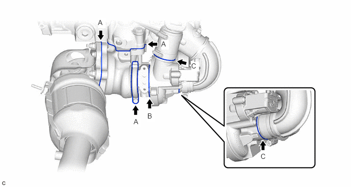
Check for oil leaks and large carbon deposits around the connecting surfaces of the turbocharger sub-assembly.
- HINT:
-
If oil leaks or a large amount of carbon deposits exist, air leaks from the respective sealing surfaces may be causing the lack of boost pressure.
- Result:
Result Proceed to An oil leak or large amount of carbon deposits does not exist. A A large amount of carbon deposits exist around the turbine housing, flange or gaskets in any of the areas (A) shown in the illustration. B A large amount of carbon deposits exist around the waste gate valve link. C Oil is leaking from between the sealing surfaces of the seal plate and compressor housing or bearing housing in the area (B) shown in the illustration. D Oil is leaking from the compressor housing in any of the areas (C) shown in the illustration. E
A
B
C
D
E
Check for loose turbine mounting nuts and for axial play in the turbine shaft.
- HINT:
-
If the turbine shaft catches or there is no play, seal failure due to seizure or improper operation due to accumulation of deposits is suspected.
- Result:
Result Proceed to No turbine shaft malfunction A Turbine shaft malfunction B
A
B
Use a vacuum pump to apply -35 +/-4.0 kPa (-263 +/-35 mmHg) negative pressure to the diaphragm chamber and check that the waste gate valve seats.
- NOTICE:
-
Do not apply a negative pressure of -65 kPa (-488 mmHg) or more to the waste gate valve actuator with bracket assembly, as doing so may damage the diaphragm.
- Standard:
Waste gate valve seats without a gap
- Result:
Result Proceed to Seats at less than -35 kPa (-263 mmHg) negative pressure A Seats at -35 kPa (-263 mmHg) or greater negative pressure B Waste gate valve does not move C
A
B
C
Check for play in the waste gate valve and waste gate valve link.
- Standard:
Play exists
- HINT:
-
Some play is required as the waste gate valve link slides. If no play exists, the valve is determined to be stuck.
Check for gaps at the waste gate valve contact surface due to scratches, deformation or wear.
- Standard:
0.15 mm (0.0059 in.) or less
- Result:
Proceed to OK NG
OK
NG
Inspect the air by-pass valve assembly.
- Result:
Proceed to OK NG
OK
NG
Check for deformation or cracks in the mounting surfaces on the exhaust manifold converter sub-assembly and the turbocharger sub-assembly.
- HINT:
-
Deformation or cracks on a mounting surface may allow exhaust gas to leak from the damaged position.
- Standard:
No deformation or cracks on a mounting surface
- Result:
Result Proceed to No problem with the mounting surface A Deformation or cracks on the exhaust manifold converter sub-assembly mounting surface B Deformation or cracks on the turbocharger sub-assembly mounting surface C
A
B
C
Replace the gasket between the exhaust manifold converter sub-assembly and turbocharger sub-assembly.
- Result:
Proceed to NEXT
NEXT
Check that the abnormal state has disappeared.
- Result:
Proceed to NEXT
NEXT
Check that the bushing of the turbine housing waste gate valve link is free of cracks and the play does not exceed 0.15 mm (0.0059 in.).
- Standard:
No cracks and play does not exceed 0.15 mm (0.0059 in.)
- Result:
Proceed to OK NG
OK
NG