NR Series FUEL FUEL PRESSURE SENSOR INSTALLATION
PROCEDURE

 23839A
1.INSTALL NO. 1 FUEL PIPE PLUG
23839A
1.INSTALL NO. 1 FUEL PIPE PLUG
Install a new O-ring, new No. 1 fuel injector back-up ring, new No. 2 fuel injector back-up ring and new No. 3 fuel injector back-up ring to the No. 1 fuel pipe plug as shown in the illustration.
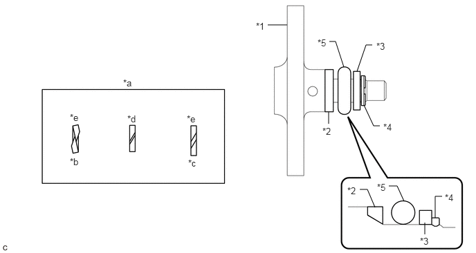
| *1 | No. 1 Fuel Pipe Plug | *2 | No. 1 Fuel Injector Back-up Ring |
| *3 | No. 2 Fuel Injector Back-up Ring | *4 | No. 3 Fuel Injector Back-up Ring |
| *5 | O-ring | - | - |
| *a | No. 1 Fuel Injector Back-up Ring Opening | *b | Overlapped |
| *c | Stretched | *d | Correct |
| *e | Incorrect | - | - |
- NOTICE:
- ·
Check that there is no foreign matter or damage on the O-ring groove of the No. 1 fuel pipe plug.
·Check that the No. 1 fuel injector back-up ring and No. 3 fuel injector back-up ring are installed in the correct orientation.
·Make sure that the No. 1 fuel injector back-up ring, No. 2 fuel injector back-up ring, No. 3 fuel injector back-up ring and O-ring are installed in the correct order.
·Check that the opening of the No. 1 fuel injector back-up ring is not overlapped or stretched as shown in the illustration.
·After installing the O-ring, check that it is not contaminated with foreign matter and is not damaged.
Install the dust cap sub-assembly to the No. 1 fuel pipe plug.
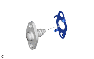
Install a new gasket to the No. 1 fuel pipe plug as shown in the illustration.
Secure the fuel delivery pipe in a vise between aluminum plates.
- NOTICE:
-
Do not overtighten the vise.
Using a 5 mm hexagon socket wrench, install the No. 1 fuel pipe plug to the fuel delivery pipe with the 2 bolts.
- Torque:
- 10 N*m (102 kgf*cm, 7 ft.*lbf)
Remove the fuel delivery pipe from the vise.
23814B
2.INSTALL FUEL PRESSURE SENSOR (FUEL DELIVERY PIPE)
- HINT:
-
Perform "Inspection After Repair" after replacing the fuel pressure sensor (fuel delivery pipe).
- NOTICE:
- ·
Do not remove the fuel pressure sensor from the fuel delivery pipe.
·If the fuel pressure sensor is removed, replace the fuel pressure sensor (fuel delivery pipe) with a new one.
3.PERFORM INITIALIZATION
Perform "Inspection After Repair" after replacing the fuel pressure sensor (fuel delivery pipe).