☰ Toyota Levin Turbo☰ فهرستAudio / Visual / Telematics › NAVIGATION / MULTI INFO DISPLAY › NAVIGATION SYSTEM(for Gasoline Model with RST Switch)
RM3660EC
_56
Audio / Visual / Telematics
_080752
NAVIGATION / MULTI INFO DISPLAY
_0391865
NAVIGATION SYSTEM(for Gasoline Model with RST Switch)
J
NAVIGATION / MULTI INFO DISPLAY NAVIGATION SYSTEM(for Gasoline Model with RST Switch) Parking Brake Switch Circuit
DESCRIPTION
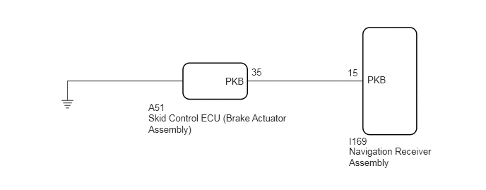
This circuit is from the parking brake ECU (brake actuator assembly) to the navigation receiver assembly.
WIRING DIAGRAM
5.125,0.99 5.583,1.188
0.458,0.198
10
false
15
5.417,1.094 5.875,1.292
0.458,0.198
10
false
PKB
5.146,2 5.604,2.198
0.458,0.198
10
false
I169
5.146,2.146 6.375,2.604
1.229,0.458
10
false
Navigation Receiver Assembly
3.323,1.115 3.781,1.313
0.458,0.198
10
false
PKB
2.188,1.656 4.292,2.125
2.104,0.469
10
false
Skid Control ECU (Brake Actuator Assembly)
3.708,0.979 4.823,1.156
1.115,0.177
10
false
35
2.188,1.5 3.479,1.833
1.292,0.333
10
false
A51
PROCEDURE
1.CHECK PARKING BRAKE INDICATOR
a.
Check that the parking brake indicator comes on when the parking brake is applied and goes off when it is released.
- OK:
The parking brake indicator operates as specified above.
- Result:
Proceed to OK NG
OK
2.CHECK HARNESS AND CONNECTOR (NAVIGATION RECEIVER ASSEMBLY - SKID CONTROL ECU (BRAKE ACTUATOR ASSEMBLY))
NG
2.CHECK HARNESS AND CONNECTOR (NAVIGATION RECEIVER ASSEMBLY - SKID CONTROL ECU (BRAKE ACTUATOR ASSEMBLY))
a.
Disconnect the I169 navigation receiver assembly connector.
b.
Disconnect the A51 skid control ECU (brake actuator assembly) connector.
c.
Measure the resistance according to the value(s) in the table below.
- Standard Resistance:
Tester Connection Condition Specified Condition I169-15 (PKB) - A51-35 (PKB) Always Below 1 Ω I169-15 (PKB) or A51-35 (PKB) - Body ground Always 10 kΩ or higher
- Result:
Proceed to OK NG
OK
PROCEED TO NEXT SUSPECTED AREA SHOWN IN PROBLEM SYMPTOMS TABLE
NG
REPAIR OR REPLACE HARNESS OR CONNECTOR