LIGHTING (EXT) STOP LIGHT SWITCH INSTALLATION
PROCEDURE

 84340
1.INSTALL STOP LIGHT SWITCH ASSEMBLY
84340
1.INSTALL STOP LIGHT SWITCH ASSEMBLY
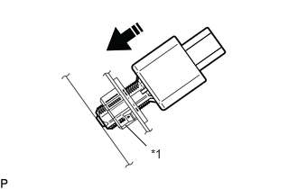
| *1 | Stop Light Switch Mounting Adjuster |

|
Insert in this Direction |
Insert the stop light switch assembly until the threaded sleeve hits the pedal as shown in the illustration.
- NOTICE:
-
When inserting the stop light switch assembly, support the pedal from behind so that the pedal is not pushed in.
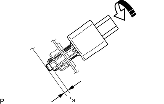
| *a | Protrusion of the Plunger |
|
|
Turn in this Direction |
Turn the stop light switch assembly 1/4 turn clockwise as shown in the illustration to install it.
- Torque:
- 1.5 N*m (15 kgf*cm, 13 in.*lbf)
or less
Connect the connector.
Check the protrusion of the plunger.
| Area | Measurement |
|---|---|
| a | 0.5 to 2.6 mm (0.0197 to 0.102 in.) |
If the protrusion is not as specified, recheck the stop light switch assembly installation and perform brake pedal adjustment if necessary.
for HV Model:
for Gasoline Model:
- NOTICE:
-
Do not depress or support the brake pedal.
87211
2.INSTALL NO. 1 AIR DUCT
55606
3.INSTALL NO. 1 INSTRUMENT PANEL UNDER COVER SUB-ASSEMBLY