NR Series COOLING COOLING FAN MOTOR INSTALLATION
PROCEDURE

 16363G
1.INSTALL COOLING FAN MOTOR LH
16363G
1.INSTALL COOLING FAN MOTOR LH
Install the cooling fan motor LH to the fan shroud with the 3 screws.
- Torque:
- 3.9 N*m (40 kgf*cm, 35 in.*lbf)
16363F
2.INSTALL COOLING FAN MOTOR RH
Install the cooling fan motor RH to the fan shroud with the 3 screws.
- Torque:
- 3.9 N*m (40 kgf*cm, 35 in.*lbf)
16361K
3.INSTALL FAN LH
- NOTICE:
-
Do not reverse the position of the fan LH and fan RH when installing them. Doing so may damage the parts.
Install the fan LH with the 3 screws.
- Torque:
- 3.9 N*m (40 kgf*cm, 35 in.*lbf)
16361J
4.INSTALL FAN RH
- NOTICE:
-
Do not reverse the position of the fan LH and fan RH when installing them. Doing so may damage the parts.
Install the fan RH with the 3 screws.
- Torque:
- 3.9 N*m (40 kgf*cm, 35 in.*lbf)
16364A
5.CONNECT COOLING FAN WIRE
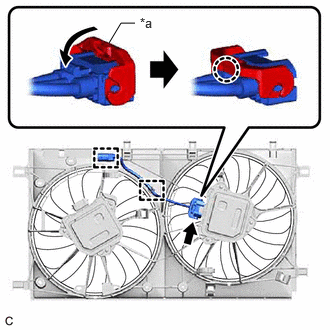
| *a | Lock Lever |
Connect the cooling fan motor RH connector.
Connect the cooling fan motor RH connector and push down the lock lever to engage the claw as shown in the illustration.
- NOTICE:
- ·
When connecting the cooling fan motor RH connector, make sure that the connecting parts of the cooling fan motor RH connector are free of dirt, water or other foreign matter.
·Be sure to securely connect the cooling fan motor RH connector.
Engage the 2 clamps to install the cooling fan wire.
6.INSTALL FAN WITH MOTOR ASSEMBLY
Engage the 2 guides.
Engage the 2 claws to install the fan with motor assembly to the radiator assembly.
- NOTICE:
-
Do not damage the radiator assembly when installing the fan with motor assembly.
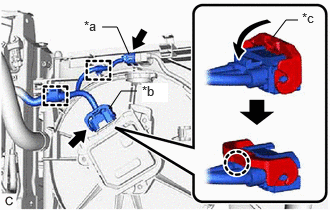
| *a | Cooling Fan Wire Connector |
| *b | Cooling Fan Motor LH Connector |
| *c | Lock Lever |
Engage the 2 clamps to connect the wire harness to the fan shroud.
Connect the cooling fan motor LH connector.
Connect the cooling fan motor LH connector and push down the lock lever to engage the claw as shown in the illustration.
- NOTICE:
- ·
When connecting the cooling fan motor LH connector, make sure that the connecting parts of the cooling fan motor LH connector are free of dirt, water or other foreign matter.
·Be sure to securely connect the cooling fan motor LH connector.
Connect the cooling fan wire connector.
16594A
7.INSTALL NO. 2 RADIATOR AIR GUIDE
Engage the 5 claws to install the No. 2 radiator air guide.
16555C
8.CONNECT NO. 5 INTERCOOLER COOLING WATER HOSE
Engage the 3 clamps to connect the No. 5 intercooler cooling water hose to the fan shroud.
Engage the 3 clamps to connect the wire harness to the fan shroud.
16572D
9.CONNECT NO. 2 RADIATOR HOSE
Engage the clamp to connect the No. 2 radiator hose to the hose clamp.
16571C
10.CONNECT NO. 1 RADIATOR HOSE
Engage the clamp to connect the No. 1 radiator hose to the hose clamp.
11.CONNECT WATER BY-PASS HOSE ASSEMBLY
Connect the water by-pass hose assembly to the radiator assembly and slide the clip to secure it.
Engage the 5 clamps to connect the water by-pass hose assembly to the fan shroud.
16640
12.CONNECT INTERCOOLER RESERVE TANK ASSEMBLY
Engage the 2 claws to connect the intercooler reserve tank assembly to the fan shroud.
Engage the 2 clamps to connect the No. 1 intercooler cooling water hose and No. 2 intercooler cooling water hose to the fan shroud.
53205
13.INSTALL UPPER RADIATOR SUPPORT SUB-ASSEMBLY
Install the upper radiator support sub-assembly with the 5 bolts.
- Torque:
- 12.5 N*m (127 kgf*cm, 9 ft.*lbf)
Engage the 3 clamps to connect the wire harness to the upper radiator support sub-assembly.
Connect the 2 horn connectors.
Engage the clamp to connect the hood lock control cable assembly to the upper radiator support sub-assembly.
17752
15.INSTALL INLET NO. 2 AIR CLEANER
Install the inlet No. 2 air cleaner to the air cleaner case sub-assembly.
17751
16.INSTALL INLET NO. 1 AIR CLEANER
Install the inlet No. 1 air cleaner to the upper radiator support sub-assembly and inlet No. 2 air cleaner with the 4 bolts.
- Torque:
- 4.0 N*m (41 kgf*cm, 35 in.*lbf)
17753
17.INSTALL INLET NO. 3 AIR CLEANER
Engage the claw.
Install the inlet No. 3 air cleaner with the 2 clips.
18.INSTALL HEADLIGHT ASSEMBLY
for TFTM Made: Click hereVehicle Exterior>LIGHTING (EXT)>HEADLIGHT ASSEMBLY (for TFTM Made)>INSTALLATION201906,202304,_59,_080784,_0393155,RM100000001HW4G,202304,999999,_59,_080784,_0393155,RM100000002B29M,
for GTMC Made: Click hereVehicle Exterior>LIGHTING (EXT)>HEADLIGHT ASSEMBLY (for GTMC Made)>INSTALLATION201906,999999,_59,_080784,_0393156,RM100000001HW4L,
161B0
19.INSTALL ELECTRIC WATER PUMP ASSEMBLY
20.ADD ENGINE COOLANT
21.INSPECT FOR COOLANT LEAK