K313 CVT VALVE BODY ASSEMBLY INSTALLATION
PROCEDURE

 35410J
1.INSTALL TRANSMISSION VALVE BODY ASSEMBLY
35410J
1.INSTALL TRANSMISSION VALVE BODY ASSEMBLY
Coat the manual valve with Toyota Genuine CVT fluid FE and install it to the transmission valve body assembly.
| *1 | Manual Valve Lever Shaft |
| *a | Knock Pin Position |
| *b | Positioning Bolt |
Align the knock pin of the transmission valve body assembly with the knock pin hole of the continuously variable transaxle assembly.
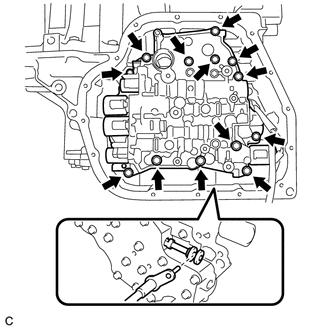
Temporarily install the transmission valve body assembly to the continuously variable transaxle assembly with the 13 bolts.
- NOTICE:
- ·
First, temporarily install the bolt marked *b in the illustration because it is a positioning bolt.
·Make sure to insert the pin of the manual valve lever shaft into the groove on the end of the manual valve.
- HINT:
- Bolt Length:
- ·
Bolt (A): 20 mm (0.787 in.)
·Bolt (B): 35 mm (1.38 in.)
·Bolt (C): 45 mm (1.77 in.)
Tighten the 13 bolts.
- Torque:
- 10.8 N*m (110 kgf*cm, 8 ft.*lbf)
Connect the temperature sensor to the transmission valve body assembly.
- NOTICE:
-
Be careful not to damage the O-ring.
Install the temperature sensor clamp to the transmission valve body assembly with the bolt.
- Torque:
- 10.8 N*m (110 kgf*cm, 8 ft.*lbf)
Connect the shift solenoid valve SLP connector.
Connect the shift solenoid valve SC connector.
Connect the shift solenoid valve SLS connector.
Connect the shift solenoid valve SLU connector.
Connect the shift solenoid valve SL connector.
35330D
2.INSTALL OIL STRAINER ASSEMBLY
Coat a new O-ring with Toyota Genuine CVT fluid FE and install it to the oil strainer assembly.
- NOTICE:
-
Ensure that the O-ring is not twisted.

Install the oil strainer assembly to the transmission valve body assembly with the 3 bolts.
- Torque:
- 10.8 N*m (110 kgf*cm, 8 ft.*lbf)
- NOTICE:
- ·
Make sure that the transmission wire is not pinched.
·Be careful not to damage the O-ring.
- HINT:
- Bolt Length:
- ·
Bolt (A): 16 mm (0.630 in.)
·Bolt (B): 25 mm (0.984 in.)
35106L
3.INSTALL TRANSAXLE OIL (CVT) PAN SUB-ASSEMBLY