K313 CVT CONTINUOUSLY VARIABLE TRANSAXLE SYSTEM Pattern Select Switch Sport Mode Circuit
DESCRIPTION
The ECM memory contains programs for normal and sport shift patterns.
By following the programs corresponding to signals from the SPORT switch (combination switch assembly), park/neutral position switch assembly and various other sensors, the ECM switches the shift control solenoid valves on and off, and controls the transaxle gear ratio.
WIRING DIAGRAM
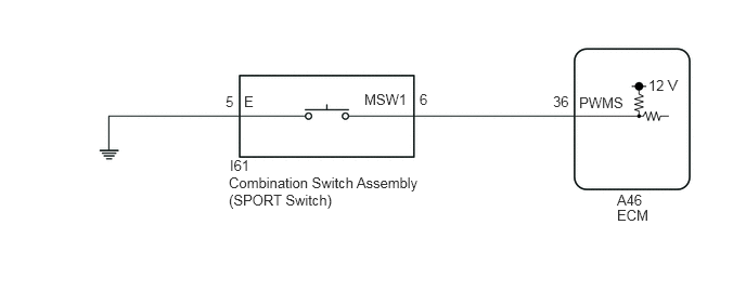
CAUTION / NOTICE / HINT
- NOTICE:
- ·
Perform initialization when parts related to the continuously variable transaxle system are replaced.
·Check that no DTCs are stored after performing initialization.
PROCEDURE
Connect the GTS to the DLC3.
Turn the ignition switch to ON.
Turn the GTS on.
Enter the following menus: Powertrain / Engine / Data List.
According to the display on the GTS, read the Data List.
- Powertrain > Engine > Data List
-
Tester Display Measurement Item Range Normal Condition Diagnostic Note Power Mode SW SPORT switch (combination switch assembly) status OFF or ON ·ON: SPORT switch (combination switch assembly) being pushed
·OFF: SPORT switch (combination switch assembly) not being pushed
-
- Powertrain > Engine > Data List
-
Tester Display Power Mode SW - 50003 372 24
- Result:
Result Proceed to Data List value is normal A Data List value is not normal B
A
B
- Result:
Proceed to NEXT
NEXT
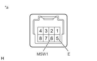
| *a | Component without harness connected
(Combination Switch Assembly (SPORT Switch)) |
Remove the combination switch assembly.
Measure the resistance according to the value(s) in the table below.
- Standard Resistance:
Tester Connection Condition Specified Condition 6 (MSW1) - 5 (E) SPORT switch (combination switch assembly) being pushed Below 50 Ω 6 (MSW1) - 5 (E) SPORT switch (combination switch assembly) not being pushed 10 kΩ or higher
Install the combination switch assembly.
- Result:
Proceed to OK NG
OK
NG
Disconnect the I61 combination switch assembly connector.
Measure the resistance according to the value(s) in the table below.
- Standard Resistance:
Tester Connection Condition Specified Condition I61-5 (E) - Body ground Always Below 1 Ω
Connect the I61 combination switch assembly connector.
- Result:
Proceed to OK NG
OK
NG
Disconnect the A46 ECM connector.
Measure the resistance according to the value(s) in the table below.
- Standard Resistance:
Tester Connection Condition Specified Condition A46-36 (PWMS) - Body ground SPORT switch (combination switch assembly) being pushed Below 50 Ω A46-36 (PWMS) - Body ground SPORT switch (combination switch assembly) not being pushed 10 kΩ or higher
Connect the A46 ECM connector.
- Result:
Proceed to OK NG
OK
NG
- Result:
Proceed to NEXT
NEXT