BRAKE CONTROL / DYNAMIC CONTROL SYSTEMS ELECTRONICALLY CONTROLLED BRAKE SYSTEM(for HV Model) C137BA2 Brake System Control Module "A" System Voltage System Voltage Low
DESCRIPTION
Refer to DTC C117A49.
| DTC No. | Detection Item | DTC Detection Condition | Trouble Area | MIL | DTC Output from | Note |
|---|---|---|---|---|---|---|
| C137BA2 | Brake System Control Module "A" System Voltage System Voltage Low | Any of the following is detected:
1.
The vehicle speed is 6 km/h (4 mph) or more and the +BS terminal voltage (soft low voltage) is less than 9.6 V for 1 second or more. 2.
The vehicle speed is 6 km/h (4 mph) or more and the +BS terminal voltage (hard low voltage) is less than 6.9 V for 1 second or more. 3.
The +BS terminal voltage is less than 6.7 V and the skid control ECU (brake actuator assembly) judges that power supply voltage is abnormal for 0.06 seconds or more. 4.
When the system has started, the +BS terminal voltage is less than 5 V for 0.5 seconds or more. 5.
The +BS terminal voltage is less than 2.6 V for 0.2 seconds or more. |
·
Wire harness or connector ·
Skid control ECU (brake actuator assembly) |
Does not come on | Brake/EPB | Output ECU: Skid control ECU (brake actuator assembly) |
WIRING DIAGRAM
CAUTION / NOTICE / HINT
- NOTICE:
- ·
Inspect the fuses for circuits related to this system before performing the following procedure.
·Before performing troubleshooting, make sure to confirm that the auxiliary battery voltage is normal.
PROCEDURE
Read the freeze frame data of DTC C137BA2.
- Chassis > Brake/EPB
-
Tester Display Measurement Item Range Normal Condition Diagnostic Note +BS Voltage +BS voltage value (value detected by ECU) Min.: 0.0 V, Max.: 25.5 V Ignition switch ON: 11.0 to 14.0 V Changes in proportion to auxiliary battery voltage
- HINT:
-
This is the voltage detected at terminal +BS (which supplies power to each solenoid) of the skid control ECU (brake actuator assembly)
+BM Voltage +BM voltage value (value detected by ECU) Min.: 0.0 V, Max.: 25.5 V Ignition switch ON: 11.0 to 14.0 V Changes in proportion to auxiliary battery voltage
- HINT:
-
This is the voltage detected at terminal +BM (which supplies power to the ABS motor) of the skid control ECU (brake actuator assembly)
- Chassis > Brake/EPB > DTC(C137BA2) > Freeze Frame Data
-
Tester Display +BS Voltage +BM Voltage - 50040 435 276,277 C137BA2
- Result:
Result Proceed to +BS Voltage and +BM Voltage are less than 9.6 V. A Only +BS Voltage is less than 9.6 V. B Only +BM Voltage is less than 9.6 V, or both +BS Voltage and +BM Voltage are 9.6 V or more. C
A
for 8ZR-FXE: Click herePower Source / Network>8ZR-FXE (BATTERY / CHARGING)>CHARGING SYSTEM>ON-VEHICLE INSPECTION202304,999999,_57,_080757,_0393175,RM1000000029OKZ,
for M20F-FXS, M20G-FXS: Click herePower Source / Network>M20F-FXS, M20G-FXS (BATTERY / CHARGING)>CHARGING SYSTEM>ON-VEHICLE INSPECTION202307,999999,_57,_146903,_0617631,RM100000002D1FU,
B
C
Turn the ignition switch to ON (READY).
Follow the instructions on the screen to display the Data List, and perform the inspection.
- Chassis > Brake/EPB > Data List
-
Tester Display Measurement Item Range Normal Condition Diagnostic Note +BS Voltage +BS voltage value (value detected by ECU) Min.: 0.0 V, Max.: 25.5 V Ignition switch ON: 11.0 to 14.0 V Changes in proportion to auxiliary battery voltage
- HINT:
-
This is the voltage detected at terminal +BS (which supplies power to each solenoid) of the skid control ECU (brake actuator assembly)
- Chassis > Brake/EPB > Data List
-
Tester Display +BS Voltage - 50003 435 276
- Result:
Result Proceed to The value of +BS Voltage is 9.6 V or more. A The value of +BS Voltage is less than 9.6 V. B
A
B
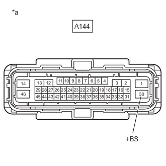
| *a | Front view of wire harness connector
(to skid control ECU (Brake Actuator Assembly)) |
Make sure that there is no looseness at the locking part and the connecting part of the connector.
- OK:
The connector is securely connected.
Disconnect the A144 skid control ECU (brake actuator assembly) connector.
Check both the connector case and the terminals for deformation and corrosion.
- OK:
No deformation or corrosion.
Measure the voltage according to the value(s) in the table below.
- Standard Voltage:
Tester Connection Condition Specified Condition A144-30 (+BS) - Body ground Always 9.6 V or higher
- Result:
Proceed to OK NG
OK
NG
Make sure that there is no looseness at the locking part and the connecting part of the connector.
- OK:
The connector is securely connected.
Disconnect the A144 skid control ECU (brake actuator assembly) connector.
Check both the connector case and the terminals for deformation and corrosion.
- OK:
No deformation or corrosion.
Measure the resistance according to the value(s) in the table below.
- Standard Resistance:
Tester Connection Condition Specified Condition A144-46 (GND1) - Body ground 1 minute or more after disconnecting the cable from the negative (-) auxiliary battery terminal Below 1 Ω
- Result:
Proceed to OK NG
OK
NG