8ZR-FXE BATTERY / CHARGING CHARGING SYSTEM ON-VEHICLE INSPECTION
PROCEDURE

 1.CHECK AUXILIARY BATTERY
Check that the auxiliary battery cables are connected to the correct terminals.
If they are not, connect them properly.
Check the auxiliary battery for damage and deformation. If severe damage, deformation or leakage is found, replace the auxiliary battery.
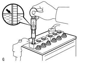
Check the electrolyte level in each cell.
If the electrolyte level is below the lower line, add distilled water to each cell. Then, recharge the auxiliary battery and check the electrolyte specific gravity.
- Standard Specific Gravity:
1.25 or higher at 20°C (68°F)
If the electrolyte level is above the lower line, check the auxiliary battery voltage when cranking the engine. If the auxiliary battery voltage is less than 11 V, recharge or replace the auxiliary battery.
- HINT:
-
Before checking the auxiliary battery voltage, turn off all the electrical systems (headlights, blower motor, rear window defogger, etc.).
2.CHECK AUXILIARY BATTERY VOLTAGE
Turn the power switch off and turn on the high beam headlights for 30 seconds. This will remove the surface charge from the auxiliary battery.
Measure the auxiliary battery voltage according to the value(s) in the table below.
- Result:
Tester Connection Condition Specified Condition Result Positive (+) auxiliary battery terminal - Negative (-) auxiliary battery terminal 20°C (68°F), Power switch off 12.0 V or higher Auxiliary battery is OK 12.0 V or less Recharge auxiliary battery
3.RECHARGE AUXILIARY BATTERY
Recharge the auxiliary battery.
- HINT:
- ·
Recharge the auxiliary battery according to the charger's instructions.
·Apply the appropriate charging current according to the type of auxiliary battery shown in the table below.
Charge Method Charging Current Normal Below 5 A Quick Below 15 A
Turn the power switch off and turn on the high beam headlights for 30 seconds. This will remove the surface charge from the auxiliary battery.
Measure the auxiliary battery voltage according to the value(s) in the table below.
- Result:
Tester Connection Condition Specified Condition Result Positive (+) auxiliary battery terminal - Negative (-) auxiliary battery terminal 20°C (68°F), Power switch off 12.0 V or higher Auxiliary battery is OK 12.0 V or less Recharge auxiliary battery
4.CHECK AUXILIARY BATTERY TERMINAL, FUSIBLE LINK AND FUSE
Check that the auxiliary battery terminals are not loose or corroded.
- Torque:
- Positive (+) Auxiliary Battery Terminal : 5.4 N*m (55 kgf*cm, 48 in.*lbf)
- Negative (-) Auxiliary Battery Terminal : 5.4 N*m (55 kgf*cm, 48 in.*lbf)
If a terminal is loose or corroded, tighten or clean the terminal.
Measure the resistance of each fusible link and fuse for the auxiliary battery charging system.
- Standard Resistance:
Below 1 Ω
If the result is not as specified, replace the fusible link or fuse as necessary.
5.CHECK AMD TERMINAL
- CAUTION:
- ·
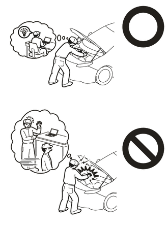
Orange wire harnesses and connectors indicate high-voltage circuits. To prevent electric shock, always follow the procedure described in the repair manual.
·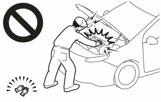
To prevent electric shock, wear insulated gloves when working on wire harnesses and components of the high voltage system.
Check that the AMD terminal is connected securely, and there is no contact problem.
If there are any arc marks, replace the affected parts.
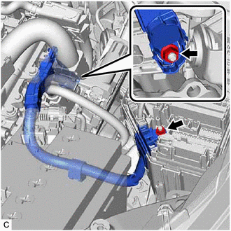
Check that the bolts for the AMD terminal are tightened to the specified torque, the AMD terminal is connected securely, and there are no contact problems.
- Torque:
- Inverter with converter assembly side:
T=16.0 N*m (163 kgf*cm, 12 ft.*lbf)
- No. 1 engine room relay block and No. 1 junction block assembly side:
T=8.4 N*m (86 kgf*cm, 74 in.*lbf)
If there are no arc marks and the AMD terminal connection is faulty, connect the AMD terminal securely.
6.CHECK DC/DC CONVERTER FUNCTION
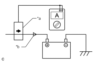
| *a | Probe Direction |
| *b | Current Flowing into Auxiliary Battery |
Connect the AC/DC 400 A probe to the positive (+) auxiliary battery cable.
Turn the power switch on (READY) and leave the vehicle as is until the electric current flowing to the auxiliary battery becomes 10 A or less.
Turn on the high beam headlights, and turn the blower motor switch to the HI position and the rear window defogger on.
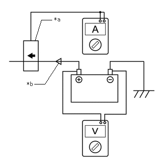
| *a | Probe Direction |
| *b | Current Flowing from Auxiliary Battery |
Measure the current and voltage according to the value(s) in the table below.
- Result:
Item Tester Connection Condition Specified Condition Current flowing from auxiliary battery Positive (+) auxiliary battery cable Power switch on (READY)
(The high beam headlights are on, the blower motor switch is in the HI position, and the rear window defogger is turned on.)0 A or less
(No current from auxiliary battery)Auxiliary battery voltage Positive (+) auxiliary battery terminal - Negative (-) auxiliary battery terminal 12.5 to 15 V
If the result is not as specified, replace the inverter with converter assembly.