BRAKE CONTROL / DYNAMIC CONTROL SYSTEMS ELECTRONICALLY CONTROLLED BRAKE SYSTEM(for HV Model) C125DA2 Electronic Brake Booster Control Module "A" Backup Power Supply Voltage System Voltage Low C125DA3 Electronic Brake Booster Control Module "A" Backup Power Supply Voltage System Voltage High
DESCRIPTION
Refer to DTC C121F87.
| DTC No. | Detection Item | DTC Detection Condition | Trouble Area | MIL | DTC Output from | Note |
|---|---|---|---|---|---|---|
| C125DA2 | Electronic Brake Booster Control Module "A" Backup Power Supply Voltage System Voltage Low | Voltage from brake control power supply assembly is less than 2.8 V for 10 seconds. | ·
Wire harness or connector ·
Electric brake booster (brake booster with master cylinder assembly) |
Does not come on | Brake Booster | Output ECU: Electric brake booster (brake booster with master cylinder assembly) |
| C125DA3 | Electronic Brake Booster Control Module "A" Backup Power Supply Voltage System Voltage High | Brake control power supply assembly power source voltage is abnormal for 10 seconds or more. | ·
Wire harness or connector ·
Electric brake booster (brake booster with master cylinder assembly) |
Does not come on | Brake Booster | Output ECU: Electric brake booster (brake booster with master cylinder assembly) |
WIRING DIAGRAM
CAUTION / NOTICE / HINT
- NOTICE:
-
These DTCs can causes fuses to burn out, so check and replace fuses as necessary after completing inspection and repairs.
PROCEDURE
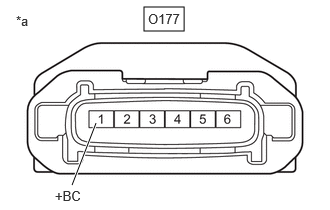
| *a | Front view of wire harness connector
(to Brake Control Power Supply Assembly) |
Make sure that there is no looseness at the locking part and the connecting part of the connectors.
- OK:
The connector is securely connected.
Disconnect the O177 brake control power supply assembly connector.
Check both the connector case and the terminals for deformation and corrosion.
- OK:
No deformation or corrosion.
Measure the voltage according to the value(s) in the table below.
- Standard Voltage:
Tester Connection Condition Specified Condition O177-1 (+BC) - Body ground Always 11 to 14 V
- Result:
Proceed to OK NG
OK
NG
Make sure that there is no looseness at the locking part and the connecting part of the connectors.
- OK:
The connector is securely connected.
Disconnect the O177 brake control power supply assembly connector.
Check both the connector case and the terminals for deformation and corrosion.
- OK:
No deformation or corrosion.
Measure the resistance according to the value(s) in the table below.
- Standard Resistance:
Tester Connection Condition Specified Condition O177-4 (GND) - Body ground 1 minute or more after disconnecting the cable from the negative (-) auxiliary battery terminal Below 1 Ω
- Result:
Proceed to OK NG
OK
NG
Make sure that there is no looseness at the locking part and the connecting part of the connectors.
- OK:
The connector is securely connected.
Disconnect the A143 electric brake booster (brake booster with master cylinder assembly) connector.
Disconnect the O177 brake control power supply assembly connector.
Check both the connector case and the terminals for deformation and corrosion.
- OK:
No deformation or corrosion.
Measure the resistance according to the value(s) in the table below.
- Standard Resistance:
Tester Connection Condition Specified Condition A143-1 (CBKP) - O177-6 (OUT) Always Below 1 Ω A143-1 (CBKP) or O177-6 (OUT) - Body ground and other terminals Always 10 kΩ or higher
- Result:
Proceed to OK NG
OK
NG